
Summary of Mail Alarm
This article details modifications to a GSM Home Alarm V1.0, upgrading it with an ESP32 microcontroller, infrared motion sensor, and keypad. The system now sends email notifications via PushingBox instead of SMS and features a custom 3D-printed enclosure.
Parts used in the Modified GSM Home Alarm:
- DFRobot FireBeetle ESP32 IOT Microcontroller
- DFRobot Gravity: Digital Infrared Motion Sensor For Arduino
- DFRobot Sealed Membrane 4*4 button pad with sticker
- DFRobot 5mm LED Pack (50 pcs)
- DFRobot 220R Resistor
- Perfboard
After completing my GSM Home Alarm V1.0 and some time of using, I decided to make some modifications.
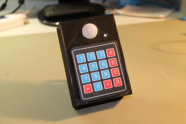
In the hardware the main changes are the replacement of the ultrasonic sensor and the introduction of a keypad. On the software, I change the SMS notification by e-mail. Also I decided to scale down the circuit and design and 3D print a box for the circuit.
Step 1: Components
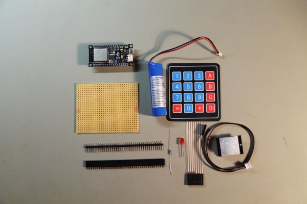
DFRobot FireBeetle ESP32 IOT Microcontroller
DFRobot Gravity: Digital Infrared Motion Sensor For Arduino
DFRobot Sealed Membrane 4*4 button pad with sticker
Perfboard
Step 2: Connect the Components
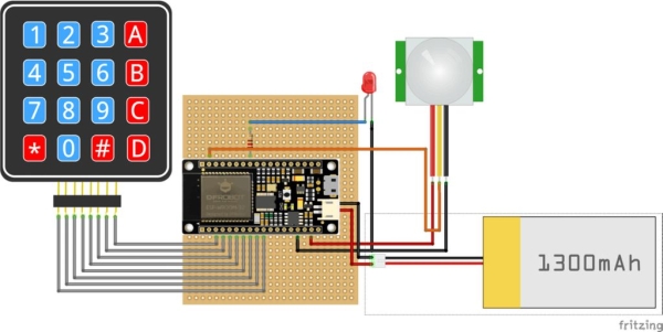
The FireBeetle ESP32 IOT Microcontroller will be the brain of this project. The big advantage is that you can get WIFI and Battery management in one very small footprint. It is powered directly from the USB port (+5V) but I also added a battery as backup power (this last one is opcional).
The keypad is connected from pin D2 to pin D8. The led is connected to pin MOSI/IO19. The PIR Sensor signal pin is connected in pin A1/IO39.
A +5V power supply (normal smartphone wall adapter) needs to be connected to the nano USB connector. One +3.7V battery can be also added as backup power.
Step 3: Pushing Box
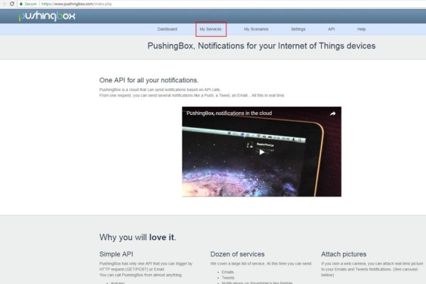
During this project I discovered this IOT service that allows you to setup several notifications.
1 – Go to https://www.pushingbox.com and create an account.
2- Go to “My Services”
3 – “Add a service”
4 – In “Email” line, press “Select this service”.
5- Configure the email that will receive the notification.
6 – Go to “My Scenarios”
7 – Press “Test”.
8 – If everything is ok, you should get an email in you inbox.
Step 4: Code
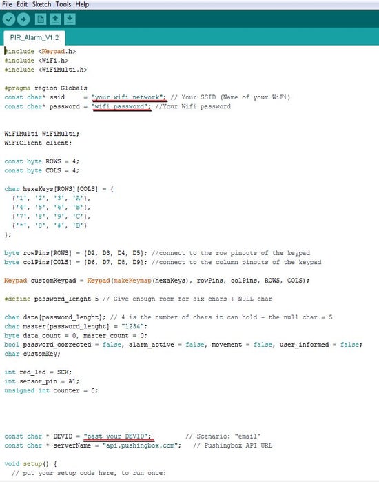
For you to use my code, some changes are necessary.
Define your WIFI network name and password.
Copy the DEVID from “My Scenarios” on Pushingbox and paste it in the code.
Upload and open a Serial Monitor window to check if everything is working.
For activating the system just press “1234”, my default password, and the alarm will be armed in 8s (this can be also changed in the code).
Source: Mail Alarm
- What components were replaced or added in the hardware modification?
The ultrasonic sensor was replaced by a digital infrared motion sensor, and a keypad was introduced. - How are the notification settings changed in the software?
The SMS notification feature was changed to send emails instead. - What service is used to setup email notifications?
The project uses the PushingBox IoT service to configure email alerts. - Which pins connect the keypad on the FireBeetle ESP32?
The keypad connects from pin D2 to pin D8. - How do you activate the alarm system using the keypad?
You press the default password 1234 to arm the system after an 8-second delay. - Can the system run without a continuous power source?
Yes, a +3.7V battery can be added as optional backup power alongside the USB supply. - Where must the DEVID be obtained for the code?
The DEVID is copied from the My Scenarios section on PushingBox. - What tool is used to design the enclosure for the circuit?
A box for the circuit was designed and created using 3D printing.
