Summary of Maximizing Productivity with an Automated Inventory Tracking System
The Automated Inventory Tracking System (AITS) is a cross-platform Flutter app and hardware solution that scans UPC barcodes, retrieves product data from the Nutritionix API, and stores user-specific inventories in Firebase to enable CRUD operations, quantity and expiration management, and search. AITS uses an ATmega328PB microcontroller with UART and an HC-05 Bluetooth module to relay barcode scans (from a Tera barcode scanner) to the mobile app, aiming to reduce food waste. Testing passed core features; push notifications failed.
Parts used in the Automated Inventory Tracking System (AITS):
- Smartphone running Flutter app (Android)
- Nutritionix API (service with API key and Secret Key)
- Firebase (users and inventory database)
- Tera Barcode Scanner (1D wireless scanner, model 5100)
- ATMega328PB microcontroller
- HC-05 Bluetooth module
- PCB with connectors and labels (J1, J2, J3, J5, U1)
- USB to mini-USB adapter / USB port (for scanner connection)
- USB to UART converter
- Mini push-button switch (S1)
- 5V power connector (J3)
- LED indicators (power, scan in, scan out)
- Female header 6 (for Bluetooth connector)
- AVR MCU programmer (Atmel 51) for SPI flashing
Abstract
The Automated Inventory Tracking System (AITS) aims to address deficiencies in the routine management of personal belongings. Specifically, it aims to minimize waste in grocery shopping by providing users with a comprehensive view of their possessions, complete with product names, specifications, and expiration dates. This initiative involves the identification of grocery item barcodes, which are then incorporated into the user’s inventory, enabling various create, read, update, and delete (CRUD) operations. The software interfaces with an API service to retrieve product details based on scanned barcodes. Subsequently, the obtained data is stored in a database, with each user having their dedicated inventory space.
1. INTRODUCTION
In 2018, the EPA reported a staggering 292.4 million tons of waste in the USA, prompting us to address this societal issue with a solution: the creation of an Automated Inventory Tracking System. Our primary objective with this project is to develop an intuitive interface that simplifies inventory management for users, ensuring ease of use and clear guidance on utilizing its features. To broaden its accessibility, we aimed to make the application platform-independent, compatible with both Android and iOS devices, catering to a wide range of users seeking advanced and efficient inventory management solutions.
Comprising software and hardware components, our system allows users to scan items they wish to add to their inventory using the hardware. Upon scanning, the software, via Bluetooth, retrieves the barcode information and displays product details on the user’s screen. The application offers various functionalities, including search, quantity adjustment, and product detail editing, empowering users to effectively manage their inventory. Furthermore, the system tracks item expiration dates, enabling users to plan ahead and minimize waste by only purchasing necessary items, thereby combating food wastage.
2. SOFTWARE APPLICATION
The software for this project was developed using Flutter, an open-source SDK (software development kit) enabling a unified codebase for multiple operating systems, thereby providing a highly convenient method to accommodate a wide range of mobile devices.
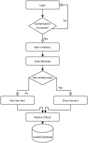
A. Workflow
The process of acquiring the software begins with downloading the application from the Google Play Store. Upon opening the app, users are directed to the login screen. We have integrated social authentication mechanisms with Gmail, simplifying the login process. When users choose to authenticate via Gmail, they are redirected to a page where they can enter their credentials. Flutter then verifies the provided email’s validity before storing it in our Firebase users table.
Our decision to prioritize Gmail authentication stemmed from our research, which indicated that over 40% of users prefer logging in through Gmail. In an effort to enhance user experience, we have implemented a silent login feature. This feature securely stores users’ email authentication details for future access, eliminating the need to re-enter credentials upon subsequent logins.
Upon successful authentication, users are directed to the main inventory interface, where they can perform various CRUD (Create, Read, Update, Delete) operations. For improved navigation, users can utilize the search functionality to locate items within the inventory, especially if the list is extensive.
The application seamlessly synchronizes with the database, allowing real-time updates as users add or scan items. This ensures that the inventory remains up-to-date and reflects any changes made by users.
B. User Interface
Each user will possess their own array of products, each comprising a collection of inventory items. Following successful authentication at the login screen, users will be directed to the primary inventory interface. This interface serves as the focal point of our application’s functionality. Users will encounter a comprehensive list of their products, featuring names, measurements, and descriptions. Clicking on individual products will reveal their respective inventory items, which include expiration dates and quantities. Prior to delving into the software development of the Automated Inventory Tracking System (AITS), we initially contemplated utilizing only a products table. However, upon conducting further analysis, we recognized the necessity of implementing a lower-level inventory items table, housing a detailed list of items along with their specific expiration dates and quantities. This necessity became evident when considering scenarios such as multiple Coca-Cola bottles, which may constitute the same product but may possess varying expiration dates. We placed significant emphasis on waste reduction and made concerted efforts to minimize it. By segregating each product into distinct inventories, we effectively addressed these concerns and aligned with our waste reduction objectives.
Upon selecting a product through clicks, users gain access to detailed information regarding each item, including expiration dates and quantities. They can adjust these quantities using the “+” or “-” buttons, with items being automatically removed from the inventory when their count reaches zero. Furthermore, if a product’s total count reaches zero, it is deleted from both the user interface and Firebase database. Users can also modify measures and expiration dates by clicking on individual items to access their details. The main inventory view features a search function allowing users to find specific products by UPC code, inventory name, etc., filtering the displayed content accordingly. This feature is particularly useful for users managing diverse inventories, minimizing manual search efforts.
Additionally, a “New Product” button in the bottom right corner enables users to create new inventory items by providing necessary details such as name, measure, expiration dates, and optional UPC codes. Upon saving, both the new inventory item and its associated product details are stored in Firebase, returning the user to the main view with the newly added product/item. The application aims for seamless integration between hardware and software via Bluetooth modules. When creating a new product, Bluetooth listeners activate, awaiting a scan. Scanned entries are automatically inserted into the UPC code field, triggering a call to the Nutritionix API for further product details retrieval.
This scanning functionality is also available within the application through a dedicated button at the top of the screen, which activates the phone’s camera for barcode scanning. Upon retrieval, the scanned string is inserted into the UPC code field, facilitating automatic extraction of product details from Nutritionix. By prioritizing user-friendliness, the application eliminates the need for additional hardware components, offering a self-sufficient solution for inventory management.
The application’s comprehensive features aim to enhance organization and optimize product usage, ultimately reducing waste and saving users time and money. By providing a comprehensive overview of their inventory, users can better plan meals, generate grocery lists, and prevent items from expiring unused. The application supports multiple users, allowing families to manage their inventory collectively across various devices. With real-time capabilities and a responsive interface, the application caters to diverse user needs across different mobile platforms.
Despite its extensive features, the Automated Inventory Tracking System (AITS) is not intended for commercial purposes. It is designed solely to benefit users and positively impact society, with plans for future updates including user alerts for approaching expiration dates and other useful functionalities. Initially available on the Google Play Store, the application may consider expansion to iOS platforms in the future, pending additional fees for App Store release.
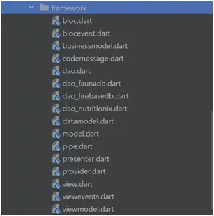
C. Framework
Our framework facilitates the seamless addition, replacement, and removal of features without requiring significant alterations to our codebase. We’ve implemented a model-based framework comprising three key components: the data model, business model, and view model. The data model encapsulates various attributes such as color, value, and name, representing entities within the system. These data models typically retrieve entity-related data from external sources, such as tables in a database.
The business model, on the other hand, represents system entities populated through multiple data models. It operates as an independent and isolated entity, utilizing data models to construct itself accurately. The view model serves as a representation of the data intended for a specific view, constructed through business logic and leveraging various business models.
Bloc events serve as triggers for business logic functions, enabling the application of necessary changes. Data access objects (Dao) facilitate the retrieval of data from the database, ensuring compatibility with data models. The presenter acts as an intermediary between the bloc and the view, facilitating communication between the two entities.
When the presenter receives an event from the view, it forwards the data to the bloc, and upon receiving an event from the bloc, it relays the data back to the view. This setup ensures smooth interaction and data flow between the various components of the framework.
D. API
The project integrates with the Nutritionix API, which boasts a database containing over 22,000 registered UPC codes. Upon creating an account, users receive an API key and Secret Key, which are then configured within the application. Subsequently, the API returns data in JSON format, encompassing all available information associated with the provided UPC code.
E. Testing
Testing was conducted with a focus on meeting the established requirements. The majority of tests were successfully completed without encountering any errors. A key aspect of testing involved verifying the functionality of CRUD operations, ensuring they operated smoothly and without issues. The API effectively retrieved data from the source and integrated it into the application. User authentication was validated, with the application successfully logging in users and displaying their specific inventory. Furthermore, the application performed well in searching for products by name using a dedicated search bar and scanning items to retrieve their barcodes.
Numerous additional tests were conducted to confirm the seamless workflow of the application. However, challenges were encountered with the notifications test. The issue stemmed from difficulties in determining the appropriate intervals required for triggers to execute notifications. A detailed breakdown of the testing process is provided in the accompanying table.
| Status | Requirements |
| Pass | The software should be able to store items from the inventory in a database |
| Pass | The software should have an API service to retrieve product details. |
| Pass | The software should be able to insert records directly from the scan and allow users to add inventory items. |
| Pass | The software should be able to delete the data |
| Pass | The software should allow the user to
add/remove expiration dates through datetime pickers |
| Pass | The application should be reusable across different platforms |
| Fail | Push Alert Notification |
3. HARDWARE APPLICATION
A. Fridge Inventory Client Tracker
The refrigerator inventory tracker required a method for inputting items placed inside the user’s fridge. Given that virtually all grocery items nowadays come with a UPC code, it was deemed advantageous to integrate a barcode scanner to facilitate tracking. Various options were considered for the user interface implementation, ultimately opting for an Android application. Since the system would operate on Android, it was determined that a microcontroller would be necessary to manage the data retrieved from the scanner and transmit it to the Bluetooth module.
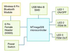
Specific criteria were established for the microcontroller, including a requirement for up to 16MIPS throughput at 16MHz, along with 32 KB ISP Flash memory featuring read-while-write capabilities. Additionally, compactness was a key consideration for the refrigerator inventory tracker hardware to ensure minimal space consumption in both kitchen and portable settings. As such, the board design was constrained to dimensions no larger than four square inches. The microcontroller interfaces with various components via pins, including three LEDs, a USB mini-B host, a push-button power switch, and a Bluetooth module pins connector, all powered by a 5V power connector as depicted in Figure 1.
The microcontroller features pins that link to three LEDs, a USB mini-B host, a push-button power switch, and a connector for the Bluetooth module. To supply power to the microcontroller and associated components, the PCB board utilizes a 5V power connector. This setup is illustrated in Figure 1.
In order to retrieve data for each grocery item stored in the fridge inventory system, a scanner needed to be integrated with the microcontroller. Various scanners were considered, many of which were connected via a lengthy USB cord. After careful evaluation, the Tera Barcode Scanner emerged as the optimal choice for several reasons. This durable, lightweight, wireless automatic single-line 1D barcode scanner not only enhances productivity but also offers scanning versatility. Additionally, it can function as a stationary desktop scanner with its included scanner holding stand.
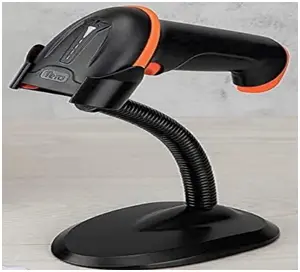
In Figure 6, the Tera Barcode Scanner, as depicted with permission from Tera Instruments, Inc., showcases a steadfast fixed-mount presentation barcode scanner. Its primary advantage lies in its seamless integration with PCs: once connected, it immediately transmits scanned barcode data to the computer, functioning akin to keyboard inputs without requiring specific drivers. This scanner is compatible with PCs and laptops, supporting plug-and-play functionality with a 2.4GHz wireless dongle. When utilizing the 2.4GHz wireless connection, it can transmit data up to 328 feet in unobstructed environments and between 30 to 100 feet indoors, depending on the complexity of the surroundings.
A notable feature introduced by Tera is the Battery Level display function in the Tera 5100 model, a unique offering in the market. This function includes four indicator light levels, with each level representing the depletion of a 500mAh battery unit. Unlike most 1D laser wireless barcode scanners with battery capacities ranging from 800 to 1200mAh, the Tera 5100 boasts an impressive 2000mAh battery capacity. Consequently, it extends operational and standby times, providing over 40 hours of continuous scanning and over 60 days of standby duration.
Establishing a connection to the UPC database is crucial for maintaining synchronized databases. In light of this, wireless network connectivity offers enhanced system integration. Choosing the appropriate medium for transmitting scanned data to update the Android App was a key consideration. Both Wi-Fi and Bluetooth modules were evaluated, with the goal of selecting a module compatible with Android devices without requiring custom drivers.
The refrigerator inventory system will be accessible to users via a smartphone application, enhancing convenience by eliminating the need for additional physical space within their homes. Leveraging the ubiquity of smartphones, which are already owned by most individuals, was deemed the optimal choice. This decision prioritizes speed and simplicity in user interaction with the system, facilitated by the utilization of UPC codes.
B. Printed Circuit Board Layout
The composition of the printed circuit board (PCB) revolves around several crucial components essential for its operation. Among these components, three interfaces play pivotal roles in ensuring the hardware functions effectively. These interfaces include the Bluetooth module, the microcontroller, and the USB port, each serving distinct functions within the system.
The Bluetooth module facilitates the transmission of barcode information to the connected cellular phone. Meanwhile, the microcontroller serves as the central processing unit responsible for receiving and transmitting signals to interpret necessary data and ensure its accurate transmission. Lastly, the USB port serves as the sole connection point for the system to interact with the scanner, enabling the retrieval of barcode information directly from the product’s surface.
On the PCB itself, these components are strategically positioned and labeled for identification. The Bluetooth module is located beneath the labels J1 and J2, while the microcontroller can be found beneath the U1 label. Similarly, the USB port is situated under the label J5. These placements and configurations are illustrated in Figure 8 for reference.
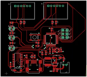
In addition to the primary hardware components mentioned above, there are other equally vital parts to consider. To enable the hardware system to activate and deactivate, a push-button switch is essential, typically identified as S1. Power is a fundamental requirement for the system to operate. Power is supplied to the board through a component labeled J3, using two female-to-male wires. Another important addition to the hardware setup is LED lights, providing visual cues to the user indicating when the board is powered on, when an item is scanned in, and when an item is scanned out.
C. Barcodes
As our project revolves around inventory tracking, a fundamental understanding of barcodes and their functionality is essential.
We have opted for simplicity in our approach and chosen to focus on one-dimensional barcodes for our project.
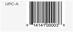
The standard term used for products is the Universal Product Code (UPC), which typically consists of a fixed string length but may vary depending on the specific product. Accessing the information linked to these barcodes necessitates entry into one of several designated databases.
Hardware
The hardware’s objective is to receive barcode data, interpret it accurately, and transmit it wirelessly to our application. The diagram provided illustrates the overall flow of data through our hardware.
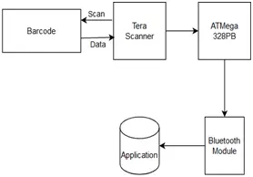
The scanner retrieves data from the barcode, which is then converted into a UART signal. This signal is transmitted to our microcontroller and subsequently relayed via our Bluetooth module.
D. UART Set up
UART, which stands for Universal Asynchronous Receiver Transmitter, is the communication protocol utilized by our hardware to interpret incoming and outgoing data. The HC-05 module we employ operates at a default baud rate of 9600, and thus, we aim for our MCU to match this baud rate. To achieve this synchronization, we employ an equation to calculate the appropriate register settings.
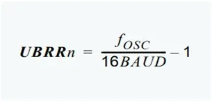
The target register value we aim to achieve is denoted by UBRRn, with a crystal frequency (FOSC) of 16MHz and a desired baud rate of 9600. Calculating this yields a decimal value of 103, which when converted to hexadecimal equals 0x67. Since UBRRn is divided into high and low bytes, the high byte is set to 0x00, and the low byte to 0x67 to attain the desired 9600 baud rate for synchronization with our Bluetooth module.
The baud rate, synonymous with bits per second, indicates the transmission speed. In UART communication, each byte transmitted requires a start and a stop bit, totaling 10 bits per byte. Consequently, the effective transmission rate should be around 960 bytes per second. Given that each string from the scanner comprises 12 characters, the total bits transmitted amount to 120 bits per string.
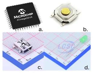
E. ATMEGA328PB Microcontroller
The core component employed in our project is the ATMega328PB microcontroller. This 8-bit microcontroller boasts 32 registers, a 1KB EEPROM, 2KB RAM, and 32KB of memory capacity.
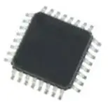
Our operation will run at a frequency of 16MHz. The primary function of this microcontroller (MCU) is to receive and process UART signals. While some MCUs support only one UART, this MCU enables multiple UART connections. To establish a successful connection with the Bluetooth component, it’s crucial to ensure that the baud rate is correctly configured to match the Bluetooth settings. This entails setting the baud rate to 9600 and incorporating this setting into the code. Additionally, we will employ SPI communication to upload code onto our ATMega. This process necessitates the use of a compatible device and software for code flashing. We have opted for the Atmel 51 AVR MCU programmer to fulfill this requirement.
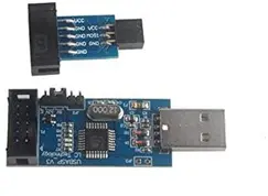
The tool operates via USB connection, linking to the SPI pins to transfer data to the MCU. Utilizing the Tera Barcode Scanner, our device is capable of scanning one-dimensional barcodes. This process involves a laser, sensor, and internal processor within the scanner. The laser reflects off the white spaces between the barcode lines, allowing the sensor to interpret the spaces and generate corresponding data.
Subsequently, this signal is transmitted through USB. For our project, we incorporate a USB to mini-USB adapter along with a USB to UART component to ensure compatibility with the required data format. Additionally, the scanner offers both wired and wireless options, enhancing its versatility and ease of use for our application.
F. HC-05 Bluetooth Module
In order to establish connectivity between our hardware and application, we’ve opted for the HC-05 Bluetooth Module. This module facilitates the transmission of barcode string data as a UART string via Bluetooth connection.
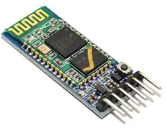
The HC-05 operates at a 9600 baud rate for establishing connections and at a 38900 baud rate for changing commands. Thankfully, there’s no requirement to modify the default settings of the Bluetooth module. The TX and RX pins correspond to UART communication, with TX transmitting data and RX receiving data. When connecting, it’s crucial to link the RX pin of the Bluetooth module to a TX pin on the MCU to ensure proper communication.
- How does AITS obtain product details after scanning a barcode?
The scanned UPC is inserted into the UPC field and the app calls the Nutritionix API to retrieve product details in JSON format. - Can users authenticate without creating a new account in AITS?
Yes, the app integrates Gmail social authentication and supports silent login to avoid re-entering credentials. - Does AITS store inventory data per user?
Yes, each authenticated user has a dedicated inventory space stored in Firebase. - What hardware transmits scanned barcode data to the mobile app?
The barcode scanner data is sent to the ATmega328PB microcontroller, then relayed via the HC-05 Bluetooth module to the app. - How does the system handle multiple items of the same product with different expiration dates?
The system uses a products table and a lower-level inventory items table to store individual items with specific expiration dates and quantities. - What baud rate is used to synchronize the microcontroller with the HC-05 Bluetooth module?
The HC-05 operates at a default baud rate of 9600 and the MCU is configured to match that rate. - Can users add inventory items manually in the app?
Yes, users can create new products/items via the New Product button by entering name, measure, expiration date, and optional UPC. - Is AITS available on iOS?
The app is initially available on Google Play Store; iOS release may be considered later pending App Store fees. - Did testing confirm CRUD and scanning functionality?
Yes, testing passed storing items, API retrieval, inserting records from scans, deleting data, editing expirations, cross-platform reuse, and search; push notifications failed.