Summary of Measuring Tempurature Using Sensor(LM35) and Atmega32
This article details a digital thermometer project using an ATmega32 microcontroller and an LM35 temperature sensor. The system reads analog voltage from the sensor via the internal 10-bit ADC, converts it to digital values with a 2.56V reference, and displays the calibrated temperature in Celsius on a 16×2 LCD.
Parts used in the Digital Thermometer Project:
- ATmega32 Microcontroller
- LM35 Temperature Sensor
- 16x2 Character LCD (HD44780)
- 1k Ohm Resistor
- Vref Potentiometer
- External Oscillator
A digital thermometer is a good project in microcontrollers because it provides an opportunity to learn using sensors to measure the real world signals that are analog in nature. I am trying to describes a similar project based on a Atmega32 microcontroller and an LM35 temperature sensor. LM35 is an analog sensor that converts the surrounding temperature to a proportional analog voltage. The output from the sensor is connected to one of the ADC channel inputs of the Atmega32 microcontroller to derive the equivalent temperature value in digital format. The calibrated temperature is displayed in a 16×2 character LCD, in both °C and °F scales.
LM35
The LM35 series of temperature sensors are produced by National Semiconductor Corporation and are rated to operate over a -55 °C to 150°C temperature range. The scale factor for temperature to voltage conversion is 10 mV per °C. The LM35 series sensors come in different packages.
The output voltage from the sensor is converted to a 10-bit digital number using the internal ADC of the aTMEGA32 Since the voltage to be measured by the ADC ranges from 0 to 1.0V (that corresponds to maximum temperature range, 100 °C), the ADC requires a lower reference voltage (instead of the supply voltage Vdd = 5V) for A/D conversion in order to get better accuracy.
Step 1: LM35 WITH ADC/DAC Temperature Calculation
In ATMEGA32A, we can give Analog input to any of eight channels of PORTA. We are going to choose channel 0 or PIN0 of PORTA. In ATMEGA32A, the ADC is of 10 bit resolution, so the controller can detect a sense a minimum change of Vref/2^10, so if the reference voltage is 5V we get a digital output increment for every 5/2^10 = 5mV. So for every 5mV increment in the input we will have a increment of one at digital output.
..
Setting the register of ADC:
1.First of all we need to enable the ADC feature in ADC.
2. Since we are measuring room temperature, we don’t really need values beyond hundred degrees (1000mV output of LM35). So we can set up maximum value or reference of ADC to 2.5V.
3. The controller has a trigger conversion feature, that means ADC conversion takes place only after an external trigger, since we don’t want that we need to set the registers for the ADC to run in continuous free running mode.
4. For any ADC, frequency of conversion (Analog value to Digital value) and accuracy of digital output are inversely proportional. So for better accuracy of digital output we have to choose lesser frequency. For lesser ADC clock we are setting the presale of ADC to maximum value (128). Since we are using the internal clock of 1MHZ, the clock of ADC will be (1000000/128).
For Ex,:
Lets assume that your other temperature measurement source is accurate at 23C.
To calibrate, adjust your Vref pot until your A/D reading is 94 ((10mV x 23)/2.5) x 1024 = 94. Oh, forget about the “+2” in your transfer function. The correct transfer function is 10mV per degree C. The “+2” is the minimum temperature that is measurable with the common pin of the sensor grounded.
Now for the scaling to convert A/D reading back to degrees C. We know that our A/D reading (with 2.5V ref) should be 94 (also assuming no errors in the A/D). So, we have 94=23. Find the scale (23/94 ~= 0.2446805). Now, we will multiply our scale by a nice binary power of 2 (256). So, our new scale is 0.2446805 x 256 ~= 63.
Now, we take our A/D reading (94) multiplied by our new scale (63). Then, after the multiplication we divide out the (256).
Final result = (94 x 63)/256 ~= 23.
There are techniques for rounding the result as well. If the accuracy of the math is not acceptable, then a larger multiplier can be used (say 65536 instead of 256).
Step 2: ADC Temperature Conversion
RED (ADEN): This bit has to be set for enabling the ADC feature of ATMEGA.
BLUE(REFS1,REFS0): These two bits are used to set the reference voltage (or max input voltage we are going to give). Since we want to have reference voltage 2.56V, REFS0 and REFS1 both should be set, by the table-1.
LIGHT GREEN (ADATE): This bit must be set for the ADC to run continuously (free running mode).
PINK (MUX0-MUX4): These five bits are for telling the input channel. Since we are going to use ADC0 or PIN0, we need not set any bits as by the table-2.
BROWN (ADPS0-ADPS2): these three bits are for setting the prescalar for
ADC. Sice we are using a prescalar of 128, we have to set all three bits.(Table-3).
DARK GREEN (ADSC): this bit set for the ADC to start conversion. This bit can be disabled in the program when we need to stop the conversion.
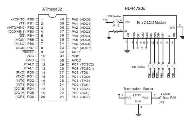
Step 3: Circuit Diagram for LM35, ATmega32,HD44780U (LCD-II)
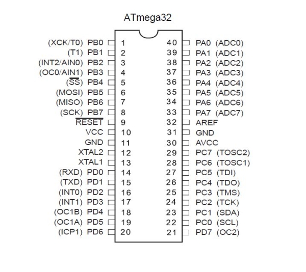
ATmega32 belongs to Atmel’s AVR series 8-bit micro controller family.
Atmega32 has is of 40 pins chip. Two for Power (pin no.10: +5v, pin no. 11: ground), two for oscillator (pin 12, 13), one for reset (pin 9), three for providing necessary power and reference voltage to its internal ADC, and 32 (4×8) I/O pins.
About I/O pins: ATmega32 is has analogue inputs. Port A can be used as either DIGITAL I/O Lines or each individual pin can be used as a single input channel to the internal ADC of ATmega32, plus a pair of pins AREF, AVCC & GND(Datasheet: Atmega32).
There is no complexity for connection. Just connect according to given Diagram……
Resistance used near lcd-V0 (1k Ohms).
Step 4: Code (Atmega32, LCD, LM35)

First of all, coding in any editor like notepad or any text-editor and compiling and loading in a toolchain:
1) Cygwin (Linux console over windows)
2) GNU Binutils
3) GCC (opensource compiler=cross compiler)
4) WinAVR (AVR Library for windows)
5) Avrdude(Burning Software into Chip)…
All these in combination works fine. We can work on any type of Atmel-Avr Chipsets using these tool chain.
You can get it from: http://winavr.sourceforge.net/
WinAVR is a suite of executable, open source software development tools for the Atmel AVR series of RISC microprocessors hosted on the Windows platform. It includes the GNU GCC compiler for C and C++.
Codes are as follows:
————————————————————————————————————————
#include “avr/io.h”
#include “temprtr.h”
#include “lcd_io.h” #include
int main() {
lcd_init();
monitor_temp();
return 0;
}
void monitor_temp()
{
lcd_clrscr();
ADMUX=_BV(REFS1)|_BV(REFS0)|0;
for(;;) {
ADCSRA= _BV(ADEN)|_BV(ADSC)|_BV(ADPS2)|_BV(ADPS1);
loop_until_bit_is_set(ADCSRA, ADIF);
display_temp(ADCW*25);
_delay_ms(1000);
}
}
void display_temp(int temp) {
lcd_gotoxy(0,0);
lcd_puts(“Temperature\n”);
lcd_puti(temp,3);
lcd_putc(‘ ‘); /* degree sign */
lcd_putc(0xDF);
lcd_putc(‘C’);
}
—————————————————————————————————————————
############################### lcd_io.h #####################################
—————————————————————————————————————————
/*LCD MODULE INFORMATION!
The maximum time required by each instruction for the slowest lcd units is 4.1 msecs for clearing the display or moving the cursor/display to the “home position”, 160 usecs for all other commands. (i use 50 because i use good units)
Usual HD44780 Pins connections
1 = Ground
2 = Vcc
3 = Contrast Voltage
4 = “R/S” _Instruction/Register Select
5 = “R/W” _Read/Write LCD Registers (See the connection table for additional information).
6 = “E” Clock
7 – 14 = Data I/O Pins 0 to 7 (0=7, 1=8,… 7=14 )
15 – Vcc for the BACKLIGHTING (Check to be sure because some units have it for Gnd)
16 – Gnd for the BACKLIGHTING (Check to be sure because some units have it for Vcc)
TYPICAL CONNECTION TABLE AS USED IN THIS lcd_io.h FILE. ACTUALLY YOU CAN USE ANY PIN AS LONG AS THE PIN CARRIES THE CORRECT SIGNAL TO THE CORRECT LCD PIN.
port_pin0 -> lcd_D4_pin11 port_pin1 -> lcd_D5_pin12 port_pin2 -> lcd_D6_pin13 port_pin3 -> lcd_D7_pin14 port_pin4 -> lcd_RS_pin4 port_pin5 -> lcd_E_pin6 GND -> lcd_RW_pin5 if lcd reading is not needed or when using mode 2 or mode 7 port_pin6 -> lcd_RW_pin5 if lcd reading is needed in mode 6 only
*/
//Program as follows:———————————-
*******************************************************************************************************/
#ifndef LCD_IO_H #define LCD_IO_H
#include #include
/*######################################################################################################*/ /* CONFIGURATION BLOCK STARTS HERE. Change these definitions to adapt setting */ /*######################################################################################################*
***********************************************************************************************/ /* GLOBAL SETTINGS (settings described here are applyied everywhere) */ /***********************************************************************************************/ /* */
#ifndef F_CPU #define F_CPU 8000000 /* CPU CLOCK FREQUENCY */ #endif
/* 6=6 PIN I/O, 2=2 PIN I/O, 3=I2C, 7=multi lcd */ #define LCD_IO_MODE 6
/* 1 = Auto line feed, 0 = no Auto line feed */ #define LCD_AUTO_LINE_FEED 0
/* THE TYPICAL TIME THE LCD NEEDS TO COMPLETE A COMMAND */ #define LCD_DELAY_TIME_US 100
/* THE E PULSE WIDTH IN MICROSECONDS (Timing is accurate)*/ #define LCD_E_PULSE_WIDTH_US 1
/* The decimal point punctuation mark char */ #define LCD_DECIMAL_POINT ‘.’
/* WAYS TO REDUCE CODE SIZE BY NOT COMPILING UNWANTED FUNCTIONS OR CODE * PORTIONS */ /* 1=function available, 0=not available. */ #define LCD_PUT_I_NEEDED 1 #define LCD_PUTS_NEEDED 1 #define LCD_PUTS_P_NEEDED 1 #define LCD_PUTS_E_NEEDED 1 #define LCD_PUTC_CGRAM_NEEDED 1 #define LCD_CLRLINE_NEEDED 1 #define LCD_GETXY_NEEDED 0 /* 1=limit, error & control chars checking disabled. Also auto line feed off. * For experts only! */ #define LCD_SAVE_MORE_CODE_SPACE 0
/*********************************************************************/ /* START OF SELECTED MODE CONFIGURATION BLOCK */ /*********************************************************************
***************************************************************************/ /* START OF MODE 6 CONFIGURATION BLOCK */ #if LCD_IO_MODE == 6 /***************************************************************************/ /* CONFIGURATION OF BELOW LINES ONLY NECESSARY IF YOU SELECTED MODE 6 IN GLOBAL SETTINGS If you plan to use just one port for all pins then just edit “LCD_PORT” otherwise you must specify the port of each lcd signal. the port(s) must be able to function as output. It can be any combination! PUT YOUR LCD PORT LETTER HERE USING CAPITAL LETTER (A,B,C,D…etc) */ #define LCD_CHARS_PER_LINE 16 /* visible chars per lcd line */ #define LCD_LINES 2 /* visible lines *
* 1=the DDR’s used are saved and restored */ #define LCD_MULTIPLEX_ENABLE 0 /* 0=use delay, 1=read busy flag & data (7 pins needed) */ #define LCD_READ_REQUIRED 0
/* This enables the backup functions that backup and restore the lcd display. LCD_LINES X LCD_CHARS_PER_LINE bytes are needed (That means 80 bytes for a 4 x 20 lcd display). 0=lcd screen backup location is eeprom, 1=lcd screen backup location is ram. If you need to backup less, use the lcd_getc function. When using the lcd_getc() function the Address Counter (AC) is auto incremented or decremented according to the ENTRY MODE selected during initialization, just like the lcd_putc() function works, so when doing a sequential read, there is no need to reposition the cursor each time a read is performed. The backup & restore settings are valid only if LCD_READ_REQUIRED == 1 */ #define LCD_BACKUP_REQUIRED 0 #define LCD_BACKUP_LOCATION 0
#define LCD_PORT C
#define LCD_DATA4_PORT D /* port for data 0 pin */ #define LCD_D4_PIN 7 /* AVR port pin number */
#define LCD_DATA5_PORT D /* port for data 1 pin */ #define LCD_D5_PIN 6 /* AVR port pin number */
#define LCD_DATA6_PORT D /* port for data 2 pin */ #define LCD_D6_PIN 5 /* AVR port pin number */
#define LCD_DATA7_PORT B /* port for data 3 pin */ #define LCD_D7_PIN 3 /* AVR port pin number */
#define LCD_RS_SIGNAL_PORT B /* port for RS line */ #define LCD_RS_PIN 1 /* AVR port pin number */
#define LCD_E_SIGNAL_PORT B /* port for Enable line */ #define LCD_E_PIN 2 /* AVR port pin number *
* YOU NEED TO EDIT “LCD_RW_SIGNAL_PORT” AND “LCD_RW_PIN” ONLY IF * “LCD_READ_REQUIRED == 1” */ #if LCD_READ_REQUIRED == 0 #define LCD_RW_SIGNAL_PORT LCD_PORT /* port for R/W line */ #define LCD_RW_PIN 6 /* AVR port pin number */ #endif
#endif /* #if LCD_IO_MODE == 6 */ /**************************************************************************/ /* END OF 6 PIN CONFIGURATION BLOCK */ /**************************************************************************
*########################################################################*/ /* CONFIGURATION BLOCK ENDS HERE. */ /*########################################################################*
* you shouldn’t need to change anything below this line *
**************************************************************************/ /* HD44780 DDRAM PARAMETERS */ /**************************************************************************/
#define LCD_LINE_LENGTH 0x40 /* internal line length */ #define LCD_START_LINE1 0x00 /* DDRAM address of first char of line 1 */ #define LCD_START_LINE2 0x40 /* DDRAM address of first char of line 2 */ #define LCD_START_LINE3 0x14 /* DDRAM address of first char of line 3 */ #define LCD_START_LINE4 0x54 /* DDRAM address of first char of line 4 *
*************************************************************/ /* INSTRUCTION REGISTER BIT POSITIONS AND COMBINATIONS */ /*************************************************************/ #define LCD_CLR 0 /* DB0: clear display */ #define LCD_HOME 1 /* DB1: return to home position */ #define LCD_ENTRY_MODE 2 /* DB2: set entry mode */ #define LCD_ENTRY_INC 1 /* DB1: 1=increment, 0=decrement */ #define LCD_ENTRY_SHIFT 0 /* DB2: 1=display shift on */ #define LCD_ON 3 /* DB3: turn lcd/cursor on */ #define LCD_ON_DISPLAY 2 /* DB2: turn display on */ #define LCD_ON_CURSOR 1 /* DB1: turn cursor on */ #define LCD_ON_BLINK 0 /* DB0: blinking cursor ? */ #define LCD_MOVE 4 /* DB4: move cursor/display */ #define LCD_MOVE_DISP 3 /* DB3: move display (0-> cursor) ? */ #define LCD_MOVE_RIGHT 2 /* DB2: move right (0-> left) ? */ #define LCD_FUNCTION 5 /* DB5: function set */ #define LCD_FUNCTION_8BIT 4 /* DB4: set 8BIT mode (0->4BIT mode) */ #define LCD_FUNCTION_2LINES 3 /* DB3: two lines (0->one line) */ #define LCD_FUNCTION_10DOTS 2 /* DB2: 5×10 font (0->5×7 font) */
#define LCD_CGRAM 6 /* DB6: set CG RAM address */ #define LCD_DDRAM 7 /* DB7: set DD RAM address */
#define LCD_BUSY 7 /* DB7: LCD is busy *
* function set: set interface data length and number of display lines */ #define LCD_FUNCTION_4BIT_1LINE 0x20 /* 4-bit interface, single line, 5×7 dots */ #define LCD_FUNCTION_4BIT_2LINES 0x28 /* 4-bit interface, dual line, 5×7 dots */ #define LCD_FUNCTION_8BIT_1LINE 0x30 /* 8-bit interface, single line, 5×7 dots */ #define LCD_FUNCTION_8BIT_2LINES 0x38 /* 8-bit interface, dual line, 5×7 dots *
* Lcd default mode used in this driver */ #define LCD_MODE_DEFAULT ((1<
/********************************************************************************************************/ /* LCD COMMANDS (CAN BE USED WITH “lcd_command(cmd);”) */ /********************************************************************************************************/ /* set entry mode: display shift on/off, dec/inc cursor move direction */ #define LCD_ENTRY_DEC 0x04 /* display shift off, dec cursor move dir */ #define LCD_ENTRY_DEC_SHIFT 0x05 /* display shift on, dec cursor move dir */ #define LCD_ENTRY_INC_ 0x06 /* display shift off, inc cursor move dir */ #define LCD_ENTRY_INC_SHIFT 0x07 /* display shift on, inc cursor move dir *
* display on/off, cursor on/off, blinking char at cursor position */ #define LCD_DISP_OFF 0x08 /* display off */ #define LCD_DISP_ON 0x0C /* display on, cursor off */ #define LCD_DISP_ON_BLINK 0x0D /* display on, cursor off, blink char */ #define LCD_DISP_ON_CURSOR 0x0E /* display on, cursor on */ #define LCD_DISP_ON_CURSOR_BLINK 0x0F /* display on, cursor on, blink char */ #define LCD_CLEAR_SCREEN (1<
/* move cursor/shift display */ #define LCD_MOVE_CURSOR_LEFT 0x10 /* move cursor left (decrement) */ #define LCD_MOVE_CURSOR_RIGHT 0x14 /* move cursor right (increment) */ #define LCD_MOVE_DISP_LEFT 0x18 /* shift display left */ #define LCD_MOVE_DISP_RIGHT 0x1C /* shift display right *
*************************************************************************/ /* LCD USEFULL DEFINITIONS */ /*************************************************************************/
#ifndef LOCATION_IS_RAM #define LOCATION_IS_RAM 1 #endif #ifndef LOCATION_IS_EEPROM #define LOCATION_IS_EEPROM 2 #endif #ifndef LOCATION_IS_FLASH #define LOCATION_IS_FLASH 3 #endif
#if LCD_IO_MODE == 7 || LCD_IO_MODE == 3 /* lcd_select() argument values */ #define ALL 0 #define LCD_0 0 #if NUMBER_OF_LCD_UNITS >= 2 #define LCD_1 1 #endif #if NUMBER_OF_LCD_UNITS >= 3 #define LCD_2 2 #endif #if NUMBER_OF_LCD_UNITS >= 4 #define LCD_3 3 #endif #if NUMBER_OF_LCD_UNITS >= 5 #define LCD_4 4 #endif #if NUMBER_OF_LCD_UNITS >= 6 #define LCD_5 5 #endif #if NUMBER_OF_LCD_UNITS >= 7 #define LCD_6 6 #endif #if NUMBER_OF_LCD_UNITS >= 8 #define LCD_7 7 #endif
#endif /* #if LCD_IO_MODE == 7 *
********************************************************************************************************/ /* PUBLIC FUNCTION PROTOTYPES */ /********************************************************************************************************
* MANUAL LCD INITIALIZATION IS NOT NEEDED ANYMORE. IT IS DONE AUTOMATICALLY! An exception is when “LCD_SAVE_MORE_CODE_SPACE == 1”. Then a call to “lcd_init()” is needed. */ /* HIGH level functions */ extern void lcd_init(void); #if NUMBER_OF_LCD_UNITS >= 2 extern void select_lcd(unsigned char lcd_unit); #endif extern void lcd_command(unsigned char cmd); extern void lcd_gotoxy(unsigned char lcd_x, unsigned char lcd_y); extern void lcd_putc(unsigned char c); extern void lcd_puts(const unsigned char *s); #if LCD_PUT_I_NEEDED == 1 extern void lcd_put_i(int value, unsigned char dot_position, unsigned char number_of_chars) ; #endif #if LCD_PUTS_P_NEEDED == 1 extern void lcd_puts_p(const unsigned char *progmem_s); #endif #if LCD_PUTS_E_NEEDED == 1 extern void lcd_puts_e(unsigned char *eeprom_s); #endif #if LCD_PUTC_CGRAM_NEEDED == 1 extern void lcd_putc_cgram(const unsigned char *user_char, unsigned char char_position); #endif #if LCD_CLRLINE_NEEDED == 1 extern void lcd_clrline(unsigned char line); #endif #if LCD_GETXY_NEEDED == 1 /* The return value of the “lcd_getxy()” function is an integer, with the high byte containing the current line number (y) and the low byte containing the char position in that line (x). If the lower byte has a value of 20 that means that you filled that line. This position result can only happen when no lcd reading is available. When lcd reading is available the maximum x == 19. */ extern unsigned int lcd_getxy(void); #endif #if LCD_READ_REQUIRED == 1 extern unsigned char lcd_getc(void); #if LCD_BACKUP_REQUIRED == 1 extern void lcd_backup_scr(void); extern void lcd_restore_scr(void); #endif #endif
/* The lcd_puti is actually a macro of the lcd_put_i(x,y,z) function with z set to 0xFF. x= the signed 16 bit number, y= the decimal digits wanted and z the number of reserved lcd chars. x must be between -32767 and +32767 and y from 0 to 5 max. z bigger than 8 is ignored and the number gets as many lcd chars as it needs (325 will get 3 lcd chars and -1 will get 2 lcd chars). Maximum char count case is lcd_put_i(-32767,5,8);. The display should show -0,32767 (8 chars) The chars are now left alligned so if you reserve lets say 5 digits for a 3 digit number like 325 then the display will show 325+space+space (Of course you can’t see the spaces).
More examples:
a) We give the command lcd_puti(var_name,0); and var=325 The display will show 325 b) We give the command lcd_puti(var_name,2); and var=325 The display will show 3,25 c) We give the command lcd_put_i(var_name,3,5); and var=325 The display will show 0,325 d) We give the command lcd_put_i(var_name,4,4); and var=325 the whole number is 0,0325 but since you reserved only 4 digits the display will show 0,03 e) We give the command lcd_put_i(var_name,1,6); and var=(-325) The display will show -32,5+space f) We give the command lcd_put_i(var_name,1,3); and var=(-325) the whole number is -32,5 but since you reserved only 3 digits the display will show -32 *
**************************************************************************/ /* FUNCTION RESEMBLING MACROS */ /**************************************************************************/
#define lcd_clrscr() lcd_command(LCD_CLEAR_SCREEN) #define lcd_home() lcd_command(LCD_RETURN_HOME) #define lcd_puti(x,y) lcd_put_i(x,y,0xFF) #define lcd_fill_cgram(array) lcd_putc_cgram((const unsigned char*)array, sizeof(array))
#if LCD_SAVE_MORE_CODE_SPACE == 1 #define lcd_goto_cgram(char) lcd_command((1<
#endif //LCD_IO_H /*######################################################################################################*/ /* T H E E N D */ /*######################################################################################################*/
Source: Measuring Tempurature Using Sensor(LM35) and Atmega32
- How does the LM35 sensor convert temperature?
The LM35 converts surrounding temperature to a proportional analog voltage with a scale factor of 10 mV per °C. - What reference voltage is set for the ADC to improve accuracy?
A reference voltage of 2.56V is set instead of the standard 5V supply to better match the sensor's output range. - Which port pin is used for the analog input?
PIN0 of PORTA, which corresponds to ADC channel 0, is chosen as the analog input. - Why is the ADC prescaler set to 128?
The prescaler is set to 128 to reduce the ADC clock frequency, ensuring better accuracy for the digital output. - How is the raw A/D reading converted to degrees Celsius?
The code multiplies the A/D reading by a calculated scale factor (e.g., 25) and divides by 256 to derive the temperature value. - What software toolchain is recommended for compiling the code?
The article recommends using WinAVR, which includes GCC, GNU Binutils, and Avrdude for Windows platforms. - Can this project display temperature in Fahrenheit?
The introduction states the device displays temperature in both °C and °F scales, though the provided code example only implements Celsius. - What mode is the ADC configured to run in?
The ADC is configured to run in continuous free-running mode so conversions occur automatically without external triggers.