Summary of Micro:bit Controlled Tic Tac Toe Game
This article details the creation of a physical Tic-Tac-Toe game using five micro:bit boards and nine SG90 servomotors. The project utilizes Tinkercad Circuits for simulation and coding, employing radio communication to coordinate between two player micro:bits and three row-controller micro:bits. The system mechanically displays "X" or "O" indicators via servo rotation while maintaining identical logic for both virtual and real-world operation.
Parts used in the Micro:bit Controlled Tic Tac Toe Game:
- 9 pieces of SG90 Servo motors
- 5 pieces of micro:bit boards
- Cardboard
- 3 color cable (or single color)
- 4 AA battery holder
- 4 AA batteries
- 5 pieces of micro:bit batteries
- Hot glue gun or adhesive material
With the addition of micro:bit to Tinkercad’s Circuits editor, it is now possible to create circuits with other Tinkercad Circuits components and to simulate the operation of the system by controlling these circuits via micro: bit. In light of this new feature, we have prepared a game that can be set up and run in the same way both in Tinkercad and the actual life.
We constituted the circuit of Tic-tac-toe game (also known as XOX) in Tinkercad and made the game work by writing its codes through the code editor embedded in Tinkercad.
Since P0, P1, P2 pins and 3V-GND outputs of micro:bit have been served in Tinkercad at the present, we have controlled three servomotors in each row by one micro:bit. In that control, we actively used radio communication as one of the most prominent features of micro:bit. At the same time; since we divided the control into parts, we created comprehensible code blocks by avoiding the confusion that may occur in the coding section.
Supplies:
The project requires:
- 9 pieces of sg90 Servo motors.
- 5 pieces of micro:bit.
- Cardboard.
- 3 color cable (One color can be used too).
- 4 AA battery holder.
- 4 AA battery.
- 5 pieces of micro:bit battery.
- Hot glue gun or another adhesive material.
Step 1: Prepare Main Board and Attach X-O Indicators
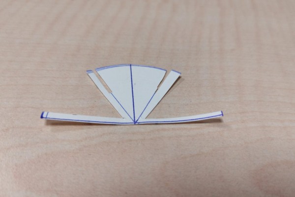
We cut half circles with a diameter of 7.5cm and positioned the letters (X-O) as shown in the second photo with the help of the sample in the first photo to show at which point X or O letter will be during the game. (You can find the printable version in the attachment.)
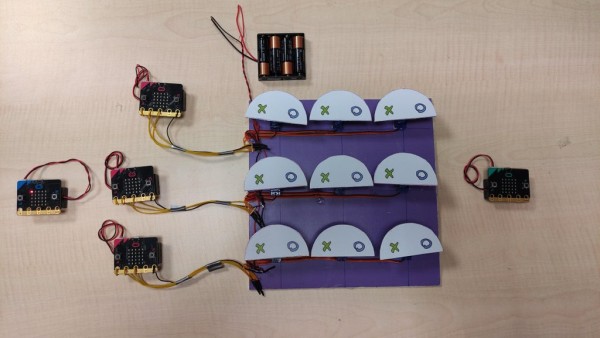
The reason for this positioning is that X and O indicators (glued on servo horn) will be rotated towards the upper part when servomotors angled 30 and 150 degrees, respectively. Thus, players will be able to see which part includes X or O. When servos remain at 90 degrees which is their initial position, the blank part of the indicator stays at the top and implies that no action has been taken in that square yet. We glued the backside of the X-O indicator and two-sided servo arms (shown in the third picture) with hot silicone as revealed in the fourth picture above. We composed a grid to constitute the playground in which servomotors will be placed. The point to be considered in composing the grid is to provide the distance that will prevent the X-O indicators (glued on two-sided servo horn) from colliding with each other when they rotated. We glued servos over the grid with a space of 7.5cm between each other since we place them in a 3×3 design. Also, we fixed servo wires in such a way as gathering them on the left side of the gameboard since all three servos per row will be controlled by one micro:bit (one out of three).
Step 2: Cut Servo Motors Cable and Attach Them Onto Board
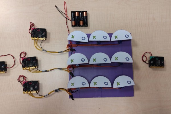
- We have connected the red (+) and brown (-) wires of all servos to each other. Thus, we will be able to provide the required power of the entire motor system through a 4-AA battery holder as revealed in the first photo. The power supplied from a 4-aa battery holder will be sufficient since one servo at the most will operate at the same time.
- To be able to control servomotors by micro:bits, we connected yellow wires of the first, second, and third servomotor to P0, P1, P2 pins, respectively. We added one more wire to each component of the GND line that we created by gathering the brown wires of all servo motors and connected them all to the micro:bits’ GND pins.
- Thus, the GND line of the system was united. While the implementation, in order not to use an expansion board or additional driver, we passed the wires through the micro:bit pin holes several times as revealed in the second photo.
- Lastly, we made the system ready both electronically and mechanically by arranging the wires as illustrated in the third photo.
Note: If the servomotors do not execute commands or vibrate even though you do everything properly, you may try to replace the batteries with new ones. As servomotors are triggered by 5V logic voltage, they may not be able to execute commands when a voltage drop on the micro:bit side occurred.
Step 3: Circuit Design on Tinkercad
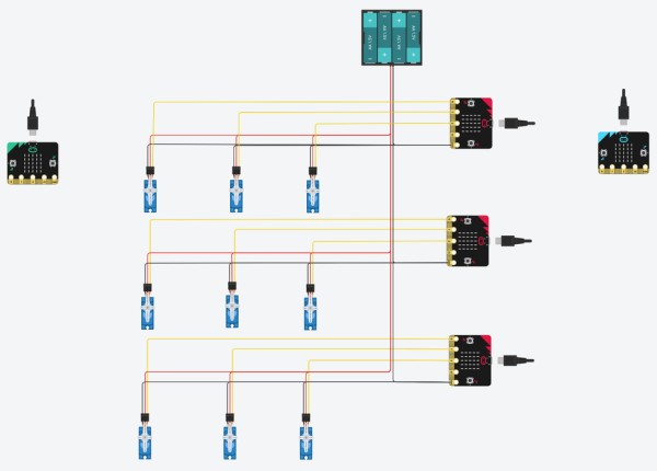
While designing the play area, we decide to make each micro:bit responsible for a single row of servo motors. Each servo motor row will be formed by three servo motors. With this design, although we use more micro:bits to form the area, we do not need to use expansion boards. And also we can use the ability to code in Tinkercad as for the time being it only give us 3 pins on the micro:bit to code.
We use 4 AA batteries to obtain the voltage we need, as we will do in real-time. On the design, we placed “X-player” micro:bit to the left-hand side, whereas “O-player” micro:bit to the right-hand side. Three micro:bits that are placed in a row will be responsible for controlling the servo motors. They will parse the messages send from the player micro:bits and turn the servo motors to a given angle in order to show X or O choices.
To finalize the circuit we combined the GND lines.
Step 4: Coding
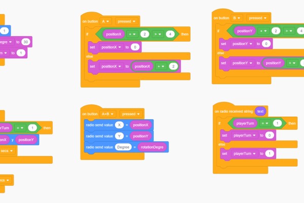
First Image – “X-player”‘s micro:bit
- “on start” block
- As we want to share messages between micro:bits via radio, first we set the radio group, which will be the same on all of the micro:bits.
- We initialize 2 variables, one for holding the rotation degree and one for indicating whether the player has to playing turn or not. For X-player as we put the “X” sign on the right side we set the “rotationDegree” variable to 30. As the game starts with the “X” we set the “playerTurn” to 1.
- “on button A pressed”, “on button B pressed” blocks
- Those blocks will change “positionX” and “positionY” variables, those 2 variables will let us know the position of the user choice. As micro:bit’s led are indexed 0 to 4 if any position variable is bigger than 4 will directly set 0. We will move among the values 0, 2 and 4.
- With “A button” we change the position on the x-axis whereas with “B button” we change the position on the y-axis.
- “forever” block
- As long as the player has the turn to play, with this block we show the indicator of players’ choice.
- “on button A+B pressed” block
- We will send the messages via radio. We will send 3 messages one for the x position of the player’s choice, one for the y position of the player’s choice, and one for the rotation degree.
- “on radio received string text” block
- As long as we receive any text message from the radio, we toggle the “playerTurn” variables value.
Second Image – “O-player”‘s micro:bit
- Every block will be the same with the “x-player”‘s micro:bit, except the initial values of variables “rotationDegree” and “playerTurn”. Set the “rotationDegree” to 150 and “playerTurn” to 0 on the “on start” block.
Third Image – “Play Area Row – 1 controller”
- “on start” block
- As we want to receive messages via radio, first set radio group to 1 as we did on players micro:bits.
- Initialize variable “rowId” to 0 as this micro:bit will control the first (top) row of servo groups.
- Turn all 3 servo motors connected to P0, P1 and P2 pins to 90 degrees. That will indicate that non of the servos are chosen by any players.
- “on radio received key value” block
- Set the “x” variable value to “value” parameter if “key” is equal to “X”,
- Set the “y” variable value to the “value” parameter if “key” is equal to “Y”.
- If “y” variable value equal to the “rowId” then, rotate the servo to “value” degrees and then send message “changeTurn” which will be handled by players micro:bits and resulted in a change on their “playerTurn” variables.
Fourth Image – “Play Area Row – 2 controller”
- Every block will be the same with the “Play Area Row – 1 controller”‘s micro:bit, except the initial values of variable “rowId”. Set the “rowId” to 2.
Fifth Image – “Play Area Row – 3 controller””
- Every block will be the same with the “Play Area Row – 1 controller”‘s micro:bit, except the initial values of variable “rowId”. Set the “rowId” to 4.
Source: Micro:bit Controlled Tic Tac Toe Game
- How many micro:bit boards are required for this project?
The project requires 5 pieces of micro:bit boards. - Can I simulate this circuit in Tinkercad?
Yes, the circuit can be set up and run in Tinkercad Circuits editor with code embedded there. - What pins on the micro:bit control the servomotors?
P0, P1, and P2 pins are used to control the three servomotors in each row. - How do the micro:bits communicate with each other?
The system uses radio communication features of the micro:bit to share messages between player and controller units. - What angle represents an X choice on the indicator?
An angle of 30 degrees rotates the indicator to show the X letter. - What angle represents an O choice on the indicator?
An angle of 150 degrees rotates the indicator to show the O letter. - How is power supplied to the servomotors?
A 4-AA battery holder provides sufficient power since only one servo operates at a time. - What happens if the servos vibrate but do not execute commands?
You should try replacing the batteries as a voltage drop may prevent execution. - Why was the grid designed with specific spacing?
The space prevents the X-O indicators from colliding when they rotate. - Which variable determines which row a controller micro:bit manages?
The rowId variable is initialized to 0, 2, or 4 to identify the top, middle, or bottom rows respectively.