Summary of Microcontroller Survivability in Space Conditions
The Utah State University experiment evaluated an ATmega328 microcontroller on an Arduino Uno board for space radiation survivability. Placed in a vacuum chamber with a Strontium-90 beta source, the device underwent ~260 krad of total ionizing dose (TID). While pin functionality remained intact, radiation caused permanent Flash memory bit flips after 186 krad and complete communication failure at 260 krad, highlighting vulnerabilities in COTS components for extended missions.
Parts used in the ArduSat Microcontroller Test:
- ATmega328 microcontroller
- Arduino Uno development board
- SST Chamber
- Sr90 beta radiation source
- Kapton-insulated graphite beaker
- High vacuum compatible USB type B cable
- Standard USB type A cable
- CoolTerm software
- 220 Ω resistors
- 100 kΩ resistors
Introduction
The Utah State University (USU) Materials Physics Group (MPG) is interested in the performance
of Commercial Off the Shelf (COTS) microcontrollers in space conditions. Microcontrollers are commonly
used on CubeSats, small relatively inexpensive satellites that are flown in Low Earth Orbit (LEO) at
altitudes of ~160 km-2000 km. There is a large area of interest in COTS microcontrollers because they
provide a more cost-effective on-board computer for CubeSats. This experiment focused on the
functionality of an ATmega328 microcontroller on an Arduino Uno board inside the MPG’s Space
Survivability Test (SST) Chamber. A diagnostic program was used to try to detect radiation effects on the
microcontroller, including both soft errors and permanent failures. ArduSats is the coined term for CubeSats
that use Arduino boards for space flight [1]. Though ArduSats are typically used for educational purposes,
the results from this research and proposed related tests could shed light on a CubeSat’s (particularly an
ArduSat’s) ability to pursue extended space missions into more radiation intensive environments such as
Geosynchronous orbits and lunar missions.
Space Environment and Effects
The main component of space environments examined in this experiment was radiation exposure;
however, the test was performed in vacuum. Different orbits expose satellites to various levels and types
of radiation. The LEO dose level is about 2 krad/yr. This is relatively low compared to the Medium Earth
Orbit (MEO) (~100 krad/yr at 2000 km-35000km) and GEO (~50 krad/yr aboave 35000 km) [2]. These
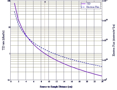
values could be assuming some minimal amount of shielding. As seen in Figure 1, some regions of space
have a high electron flux, such as LEO, but the energy of these electrons is relatively low. This means that
the microcontroller can be protected from a large portion of these electrons with very minimal shielding.
Microprocessors can experience failures ranging from soft errors to total system failure due to
radiation effects. A soft error, also known as a single-event
upset (SEU), is when radiation causes enough of a charge
disturbance to alter the state of a memory bit. These are called

space environments (Sr90 source is ~200keV-~2MeV) [3].
setup.
soft errors because they are repairable, and the system is still functional after an SEU. There are both
multibit upsets and single bit upsets, but the latter is more common [4]. A single-event effect (SEE) happens
when high-energy particles in the space environment strike the components of the microcontroller circuit
[5]. An SEE can cause a range of damage including, no observable effect, a transient disruption of circuit
operation, a change of logic state, or even permanent damage to the device or integrated circuit (IC) [5].
The microelectronic circuits in this experiment are particularly susceptible to radiation because of
their physical size. They are small enough that an energetic particle can change the device state or destroy
a trace. In some cases, these high-energy particles can even destroy portions of the microcontroller’s
memory . Beta radiation hits these circuits with electrons, causing the SEE’s. The long-term damage done
by radiation in space environments is typically due to the total ionizing dose (TID), which is the total
amount of radiation an object is exposed to.
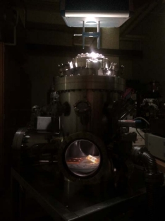
Chamber Capabilities
The SST chamber (Figure 2) contains ~100 mCi Sr90 beta radiation source (Figure 3) that provides
a dose rate of ~0.1 krad/hr at a 30 cm distance over a 15 cm diameter sample area [3]. This dose rate
provides an upper bound approximation of the dosing rate in GEO with minimal shielding. To expedite the
testing process, the distance to the radiation source can be decreased; this relationship is shown in Figure
- Since the dose rate was only important as it related to the total ionizing dose (TID), the Arduino board
with dimensions of ~7cm x ~5.5 cm was moved to ~9 cm from the source, increasing the TID rate to ~0.991
krad/hr, but decreasing the diameter of a uniform dose to ~4.5 cm. The ATmega328 chip was centered
under the source since this experiment was focused on the microcontroller There are many instrumentation
cabling feedthroughs available on the SST chamber, including both USB and D-pin serial adapters, able to
accommodate a maximum voltage of 100 V and a maximum current of 1 A.
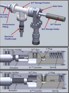
Cutaway views while in the (b) closed
and (c) exposure positions [3].
respectively
Microcontroller Design
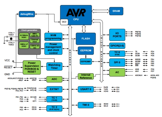
The microcontroller used in this experiment was an ATmega328 on the Arduino Uno development
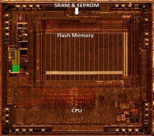
board (Atmel, ATmega328/P). There are three types of memory associated with this microcontroller: Flash,
SRAM, and EEPROM (Table 1). As can be seen in Figures 5 and 6, the Flash memory is physically the
largest memory portion of the chip, which makes it the most susceptible of the three memory sections to
radiation damage. The Flash memory is where the program is uploaded and stored in the microcontroller.
This memory is divided into two physical regions: the Boot Loader and Application section [5]. The Boot
Loader section contains firmware that aids in programming the microcontroller when using the Arduino
Integrated Development Environment (IDE). This leaves the Application section to store any program that
is written to the microcontroller [6]. Flash memory is non-volatile memory which means the information
stored there remains even when the power is turned off. Static Random Access Memory or SRAM is the
portion of memory used by the program to create and manipulate variables. Unlike the Flash memory, the
SRAM is volatile memory, meaning that all information stored there is deleted every time the
microcontroller is turned off. Lastly, the electrically erasable programmable read-only memory (EEPROM) is dedicated space to save long-term information, making it non-volatile memory. Since there is a high volume of open source
Arduino code on the internet, code was taken and modified for the purposes of this experiment. The
bulk of this code was left unchanged from what was found online. The original code was created by Terry King and can be found at arduinoinfo.wikispaces.com/Arduino_Test. The program used assumes that pins 0, 1, and 13 work if the
program can be uploaded and if the on-board LED can blink, therefore this program does not test these
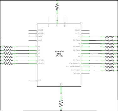
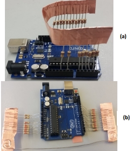
pins. Digital pins 2-12 and analog pins A0-A5 each had 220 Ω resistors connected to each other in parallel.
These resistors were then connected in series to the 5-Volt power supply and the ground through 100 kΩ
resistors (see Figures 7 and 8). The circuit design created a voltage divider that provided each of the
common points with 2.5 V when the pins were set to high input. The code runs a total of three types of tests
to ensure that all the pins were functioning properly.
The first test uses the first analog pin (A0) to see if the common points are at anything besides 2.5
V, which would indicate that a pin was stuck in a High or Low state or is not properly set to either state.
The next type of test sets pins 3-A5 to the High or Low state and setting pin 2 to the opposite state. Each of the pins
are individually tested against pin 2 and must be able to sink or source the proper amount of current to pass the
test. The last type of test verifies that the analog pins read out the correct voltages when supplied with various
voltages. If any failures are detected by the program, they are then summed and a read out of how many failures
occurred during the test is displayed at the end of the print out. A delay function is at the end of the code to
allow the user to run the code at whatever the desired frequency is. This program takes ~2 seconds to run
through all the tests and output the data. This code is named King_Olsen_Diagnostics.ino and can
be found in the raw data compressed file given separately.
The Arduino IDE was the code writing environmentused in this project. Although Arduino IDE allows programs to output data to the Serial Monitor, the output is not archived anywhere. Therefore, the only way to save information from the Serial Monitor is to copy and paste the output into a text file once data is acquired. This is not the most reliable way to save the data because if the Serial Monitor is closed for any reason during the test, all that data is lost. Therefore, the Serial Monitor was only used for quick checks to ensure that the program was
performing properly and another program called CoolTerm from www.freeware.the-meiers.org was used to save the data. CoolTerm allowed for the user to record the data to a text file and monitor the program at the same time. Another necessary feature for archiving the data was parallel serial monitoring. The Arduino IDE only allows for one Serial Monitor window to be open at a time while CoolTerm allowed the user to run, watch, and save data from two different setups at once. This feature was important because while an Arduino was being tested in the chamber (referred to as the “test Arduino”), an identical setup was being tested outside the chamber without
radiation exposure (referred to as the “control Arduino”) and both of their data needed to be recorded. The control Arduino provided information about how the microcontroller performed of an extended period without radiation
exposure. CoolTerm also allowed all of the data to be timestamped as it was being saved into a text
document.
How frequently the diagnostic code is running is directly related to the probability of recording a
soft error. As previously mentioned, SEU’s are temporary failures in the system being tested, which makes
them more difficult to test. Simply taking more data helps in the detection of these soft errors. If the test is
running less frequently, then the SEU could occur and the affected bit could go back to normal before the
program is run again. The program was set to run every fifteen minutes and it took 2 seconds to complete.
Therefore, the Arduino was only being tested 8 secs/hr or 1/450 of the testing duration.
(b) Chamber setup
Testing
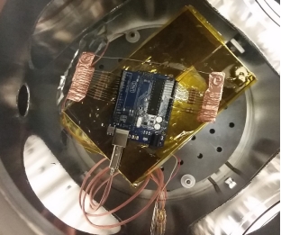
The chamber Arduino was placed on top of a large beaker with a piece of Kapton-insulated graphite
inside the SST Chamber (Figure 9) to increase the TID rate to ~1 krad/hr. Because the main objective was
to test the microcontroller, the Arduino was positioned so the ATmega328 chip was centered under the
radiation source. The Arduino communicated with the computer via a ~58 cm USB type B cable (Figure
10) designed for this experiment. The high vacuum compatible cable was made of four Kapton-insulated
wires that were braided into two wire pairs to minimize ground loop noise and put inside a coaxial copper
braided sleeve. The end of the cable opposite to the Arduino had pins sockets that connected to the vacuum
electrical feedthrough pins inside the chamber. On the outside of the chamber, a ~185 cm standard USB
type A cable with four pins was connected to the computer and the corresponding pins on the outside
vacuum electrical feedthroughs.
The diagnostic code was tested with a 1 second delay while the vacuum chamber pumped down to
a pressure of ~1.7×10⁻⁷ torr and the radiation source was not in place. The delay was then changed to 10
seconds with the closed source inserted into the chamber. The source was then opened and the Arduino was
chamber.
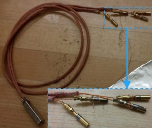
sockets used for the cabling feedthrough.
monitored in this configuration for 35 minutes. Finally, the delay was set to run once every 15 minutes, to
keep the amount of data to a reasonable amount, presumably until a failure was observed. A control Arduino
outside the chamber followed these same configurations for the entirety of the test.
Results
After ~188 hours of exposure (~186 krads), the diagnostic code had not detected any pin failures
while running in 15 minute intervals. In an attempt to detect SEU’s, it was proposed to reupload the program
with a shorter delay. The 15 minute delay was replaced with a 10 second delay. However, when trying to
upload the adjusted code, an error message was produced. This error message read “avrdude: verification error,
first mismatch at byte 0x133f 0xea != 0xe6; avrdude: verification error; content mismatch; avrdude: verification error; content mismatch”. An error such as this indicates an issue in either the memory or communications with the computer. The same error message was produced with each attempt at uploading any sort of code
to the test Arduino. Also, the diagnostic code was successfully uploaded to a third Arduino. These exercises ruled out a
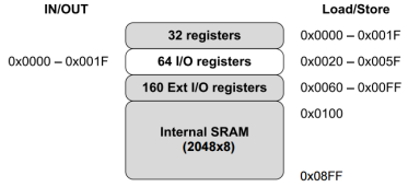
communications issue, leaving a failure in the memory. The location of the mismatched byte is given in the message as
0x133f, 4927 in decimal. From examining the memory maps of
memory [6].
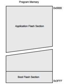
the SRAM (Figure 11) and the Flash memory (Figure 12), the location of this error can be narrowed down
even further. SRAM contains addresses ranging from 0x0000-0x08ff, 0-2303. This range is not large
enough to contain the location of the problem byte. Flash memory contains addresses from 0x0000-0x3fff,
0-16383. The EEPROM is left for the user to store data, so a program does not use this memory unless it is
written into the code, which was not the case for this program. Therefore, the mismatched byte must be in
the Flash memory. It makes sense that an error would occur here because of the physical size of the flash
memory. The portion of the error message that says “0xea != 0xe6” is indicating that the bootloader found
binary 1110 1010 instead of 1110 0110. This means that two bits are in the wrong state. Since the error was
identical every time the program was uploaded, it can be assumed that these bits were permanently stuck
in the wrong state.
The program continued to run a diagnostic test at 15 minute intervals until the Arduino stopped
writing to the computer after ~263 hours (~260 krads). The diagnostic program did not show a single pin
failure throughout the entire test, however errors did occur.
Conclusions & Future Work
In conclusion, the diagnostics program never indicated pin failures although the TID from this test
was on the same order of magnitude of the TID during a year in MEO. However, an error did arise when
trying to upload code to the Arduino after ~186 krads of exposure. This error was caused by two bits in the
Flash memory being stuck in the wrong state. Also, the Arduino stopped writing to the computer after being
exposed to ~260 krads. Although the pins seemed to still be operational in the MEO and GEO ranges, the
memory was affected and further investigation into the consequences of these effects would be pertinent to
CubeSat flights.
Source: Microcontroller Survivability in Space Conditions
- What is the primary goal of this experiment?
To evaluate the performance of Commercial Off the Shelf microcontrollers in space conditions. - How frequently was the diagnostic code running during the test?
The program was set to run every fifteen minutes. - Does the Arduino IDE allow saving Serial Monitor data automatically?
No, the output is not archived anywhere and must be manually copied or saved using other tools. - Which memory type is most susceptible to radiation damage?
Flash memory is the most susceptible because it is physically the largest portion of the chip. - What specific error occurred after 186 krads of exposure?
An upload verification error indicating two bits were stuck in the wrong state within the Flash memory. - Can soft errors be detected by simply increasing the testing frequency?
Yes, taking more data helps detect soft errors that might resolve before the next test cycle. - Why was CoolTerm software used instead of just the Arduino IDE?
CoolTerm allowed for parallel serial monitoring and automatic timestamped data archiving. - What distance was used between the sample and the radiation source?
The Arduino board was moved to approximately 9 cm from the source to increase the TID rate.