The user interface has the following parts.
Output Device: A 16×2 alphanumeric LCD Module is used as the main output device. It can display numbers, alphabets and few symbols. It can show two line and each line can have 16 characters. The backlight enables the text to be visible even in dark.
A buzzer beeps when the system receive input from the user and the input is successfully processed. For example if the user presses 10 MIN button to increment timer by 10 min and this is successfully carried out the buzzer beeps. But if the timer is already at the maximum setting (90 minutes) the operation could be carried out, so the buzzer does not beeps.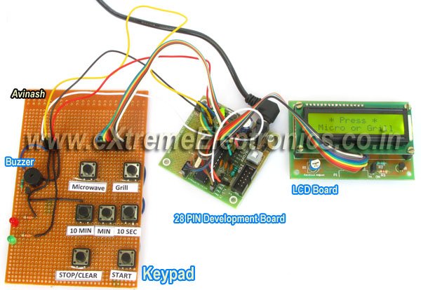
This buzzer also beeps a few time when the food is ready (countdown is finished)
Input Device: Input from user is received by a keypad which has seven push buttons. The details of button is given below.
| Button | Function |
| Microwave | Selects Microwave mode. |
| Grill | Selects Grill mode. |
| 10 MIN | Increment timer by 10 minutes. |
| MIN | Increment timer by 1 minute. |
| 10 SEC | Increment timer by 1 sec. |
| STOP/Clear |
|
| START |
|
Controlling Relays
Their are two controlling relay
- The microwave relay: this controls power to the microwave function.
- The grill relay: this controls the power to the grill function.
Using the Microwave Timer
The first screen of timer asks you to choose one of the operating modes. You can choose from Microwave or Grill functions. Press the respective button on the keypad to choose the mode.
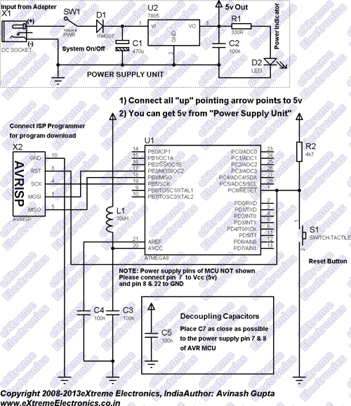
Hardware for Microwave Timer
The timer is built around ATmega8 AVR microcontroller. This is a very small single chip computer which runs a small program stored in its flash memory. This program provides all the functionalities of the timer.
Our microcontroller controls the LCD Module, the relays and the buzzer. It receives user input from the keypad.
MCU Core
Microcontroller chip requires a basic circuitry for functioning. This consists of the following parts.
- Power supply: This provides 5v regulated DC power to the microcontroller. It receives input 12V DC from a 12V adapter.
- ISP Header: In circuit programming header. Used to easily connect an ISP Programmer to upload programs to the Microcontroller.
- Reset Circuit: A pull up resistor holds the RESET pin of MCU to high state. This is required for normal operation.
For more detail: Microwave Controller using ATmega8 – AVR Project