Summary of Stepper motor control with an ATmega8 microcontroller
This note outlines designing and assembling a stepper motor system using an ATmega8 microcontroller, including theory (4-phase motors, phasing, step angle), hardware simulation in Proteus, PCB design with Altium (4lead stepper.prjpcb), and control software provided in a code folder. It explains using transistor drivers to interface the MCU to motor windings and notes the original application for a car sliding door in a 4-floor elevator project.
Parts used in the Stepper motor system project:
- ATmega8 microcontroller
- 4-phase (4-wire) stepper motor
- Transistors for winding drivers
- Proteus simulation software (for hardware simulation)
- Altium Designer PCB project file (4lead stepper.prjpcb)
- PCB fabrication service (board fabricator)
- Power supply for motor and controller
- Connecting wires and common wiring for windings
- Supporting passive components (resistors, capacitors as needed)
This note provides basic implementation details and procedural information to design and assemble a stepper motor system. The controller discussed here is the ATmel mega8, an 8-bit microcontroller (MCU).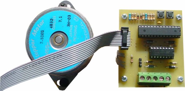
The note consists of a general description and gives highlights of implementing a basic stepper motor system application. To amplify the application, the software was generated using Atmel mega8 microcontroller. The program created with the controller is shown in “Control software Explanation” section of this note. For convenience, a copy of the code is available and is included in a folder name “code”. For the sake of this note being educational, the hardware was also simulated with Proteus software prior to design of PCB. Code folder includes a file name 4lead stepper.prjpcb designed with Altium layout software. You may get the PCB of the controller circuit built by placing an order with any board fabricator.
Stepper motor theory
Originally, this controller was designed to control a car’s small sliding door related to the 4 Floor Elevator system project. As it is mentioned in that project, in the up graded version, I used a 4 wire stepper motor to open or close the sliding door.
A 4-phase stepper motor is really two motors sandwiched together. Each motor is composed to two windings. Wires connect to each of the four windings of the motor pair, so there are eight wires coming from the motor. The commons from the windings are often ganged together, which reduces the wire count to 4, 5, or six instead of eight.
Stepper Phasing
A 4-phase stepper motor requires a sequence of four pluses applied to its various windings for proper rotation. By their nature, all stepper motors are at least two-phase. The majority are 4-phase, some are six phase. Usually, but not always, the more phases in a motor, the more accurate it is.
Step Angle
Stepper motors vary in the amount of rotation the shaft turns each time a winding is energized. The amount or rotation is called the step angle and can vary from as small as 0.9 degrees to 90 degrees. The step angle determines the number of steps per revolution. A stepper with a 1.8 degree step angle, for example, must be pulsed 200 times for the shaft to turn one complete revolution. A stepper with a 7.5 degree step angle must be pulsed 48 times for one revolution, and so on.
Controlling a Stepper motor
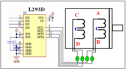
Steppers have been around for a long time. In the old days, stepper motors were actuated by a mechanical switch, a solenoid-driven device that pulsed each of the windings of the motor in the proper sequence. Now, stepper motors are invariable controlled by electronic means. Basic actuation can be accomplished via computer control by pulsing each of the four windings in turn. The computer can not directly power the motor, so transistors must be added to each winding, as shown in figure 1.
 For more detail: Stepper motor control with an ATmega8 microcontroller
- What microcontroller is used in the project?
The ATmega8 8-bit microcontroller is used in the project. - How many phases does the stepper motor have?
The project uses a 4-phase stepper motor. - Can the microcontroller directly power the stepper motor?
No, the microcontroller cannot directly power the motor; transistors are used to drive each winding. - What software was used to simulate the hardware?
Proteus software was used to simulate the hardware prior to PCB design. - Is the control code provided with the project?
Yes, the control software is provided in a code folder included with the note. - What PCB design file is included?
The code folder includes an Altium PCB project file named 4lead stepper.prjpcb. - What determines the number of steps per revolution?
The motor step angle determines the number of steps per revolution (e.g., 1.8 degree equals 200 steps). - Was this controller used in any application example?
Yes, it was originally designed to control a car’s small sliding door in a 4 Floor Elevator system project.