
Summary of Interfacing DC Motor with Atmega32 Microcontroller
This article explains how to control a DC motor using an Atmega32 microcontroller by addressing current limitations, back EMF, and voltage mismatches. It recommends using the L293D or L293 IC as a quadruple half H-bridge driver instead of building a discrete transistor circuit. The guide details connecting the motor supply (Vs) and logic supply (Vss) while enabling drivers via EN1 and EN2 pins to manage direction and speed.
Parts used in Interfacing DC Motor with Atmega32 Microcontroller:
- Atmega32 Microcontroller
- L293D IC
- DC Motor
- Freewheeling diodes (internal to IC)
- Transistors (if building custom H-Bridge)
- Resistors (if building custom H-Bridge)
In some of your electronic projects you may want to control a DC Motor with Atmega32 Microcontroller. We can’t connect a DC Motor directly to a microcontroller due to following reasons.
- A microcontroller can’t supply the current required for the working of DC Motor. ATmega32 Microcontroller can source or sink currents up to 40mA but a DC Motor needs current very much more than that.
- The negative voltages created due to the back emf of the motor may affect the proper functioning of the microcontroller.
- You may need to control the direction of rotation of the motor by changing the polarity of the motor supply.
- The operating voltage of the DC Motor may be much higher than the operating voltage of the microcontroller.
To solve these problems you may use transistorized H Bridge in which freewheeling diodes are used to avoid problems due to back emf. Thus it requires minimum four transistors, diodes and resistors for each motor. It is better to use readymade ICs such as L293D or L293 instead of making your own H Bridge, which simplifies your project.
L293D is a Quadruple Half H-Bridge driver commonly used for motor driving. We needn’t connect any transistors, resistors or freewheeling diodes. All the four outputs of this IC are TTL compatible and output clamp diodes are provided to drive inductive loads. L293D can provide up to 600mA current, in the voltage raging from 4.5 to 36v. L293 is a similar IC which can provide up to 1A in the same voltage range.
L293 or L293D contains four Half H Bridge drivers and are enabled in pairs. Input EN1 is used to enable pair 1 (IN1-OUT1, IN2-OUT2) and input EN2 is used to enable pair 2 (IN3-OUT3, IN4-OUT4). We can drive two DC Motors with one L293D, but here for demonstration we are using only one. You can connect second DC Motor to driver pair 2 according to your needs.
Circuit Diagram
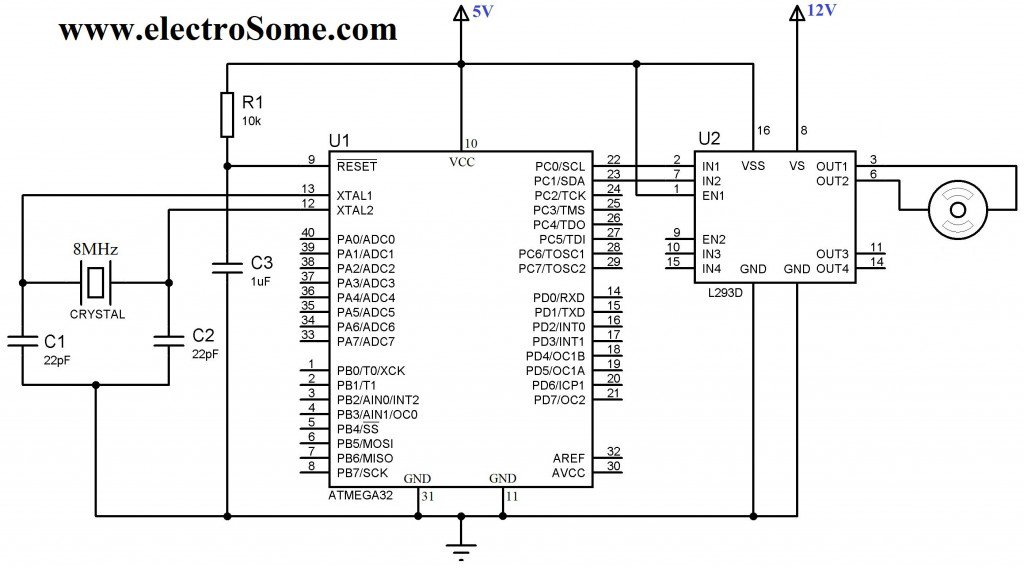
Motor Supply is given to the Vs pin of L293D and motor is connected to the first pair of drivers, which is enabled by connecting EN1 to logic HIGH. Vss pin is used to provide logic input to L293D. Control signals is given by using Atmega32 microcontroller which operates at 5V, hence Vss is connected to 5V.
For more detail: Interfacing DC Motor with Atmega32 Microcontroller
-
Why can't a DC motor be connected directly to the microcontroller?
The microcontroller cannot supply the required current, back EMF may affect functioning, polarity changes are needed for direction, and operating voltages often differ. -
What is the recommended solution for controlling a DC motor with an Atmega32?
Use readymade ICs such as L293D or L293 instead of making your own H Bridge to simplify the project. -
How many DC motors can one L293D drive?
You can drive two DC motors with one L293D because it contains four Half H Bridge drivers enabled in pairs. -
What is the function of the EN1 pin on the L293D?
Input EN1 is used to enable pair 1 which consists of IN1-OUT1 and IN2-OUT2 connections. -
What voltage range does the L293D support?
The L293D operates in a voltage range from 4.5 to 36v. -
How should the Vss pin be connected if the microcontroller operates at 5V?
Vss is connected to 5V because the control signals come from the Atmega32 microcontroller which operates at 5V. -
Does the L293D require external freewheeling diodes?
No, output clamp diodes are provided within the IC to drive inductive loads so you do not need to connect any external diodes.
