
Summary of Interfacing LCD with Atmega32 Microcontroller using Atmel Studio
This article explains interfacing a 16×2 character LCD with an Atmega32 microcontroller using a custom library in Atmel Studio. It details the differences between 8-bit and 4-bit communication modes, highlighting that 4-bit mode saves pins despite being slightly slower. The text outlines specific initialization and control functions provided in the `lcd.h` header file, such as clearing the screen, setting cursors, writing characters or strings, and shifting display data.
Parts used in Interfacing 16×2 LCD with Atmega32:
- 16×2 Character LCD module
- Atmega32 Microcontroller
- Atmel Studio software
- lcd.h header file
As we all know LCD (Liquid Crystal Display) is an electronic display which is commonly used nowadays in applications such as calculators, laptops, tablets, mobile phones etc. 16×2 character LCD module is a very basic module which is commonly used by electronic hobbyists and is used in many electronic devices and project. It can display 2 lines of 16 character and each character is displayed using 5×7 or 5×10 pixel matrix.
Interfacing 16×2 LCD with Atmega32 Atmel AVR
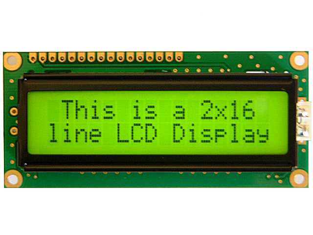
Microcontroller using Atmel Studio is bit complex as there is no built in libraries. To solve this difficulty we developed a LCD library which includes the commonly used features. Just include our header file and enjoy. You can download the header file from the bottom of this article.
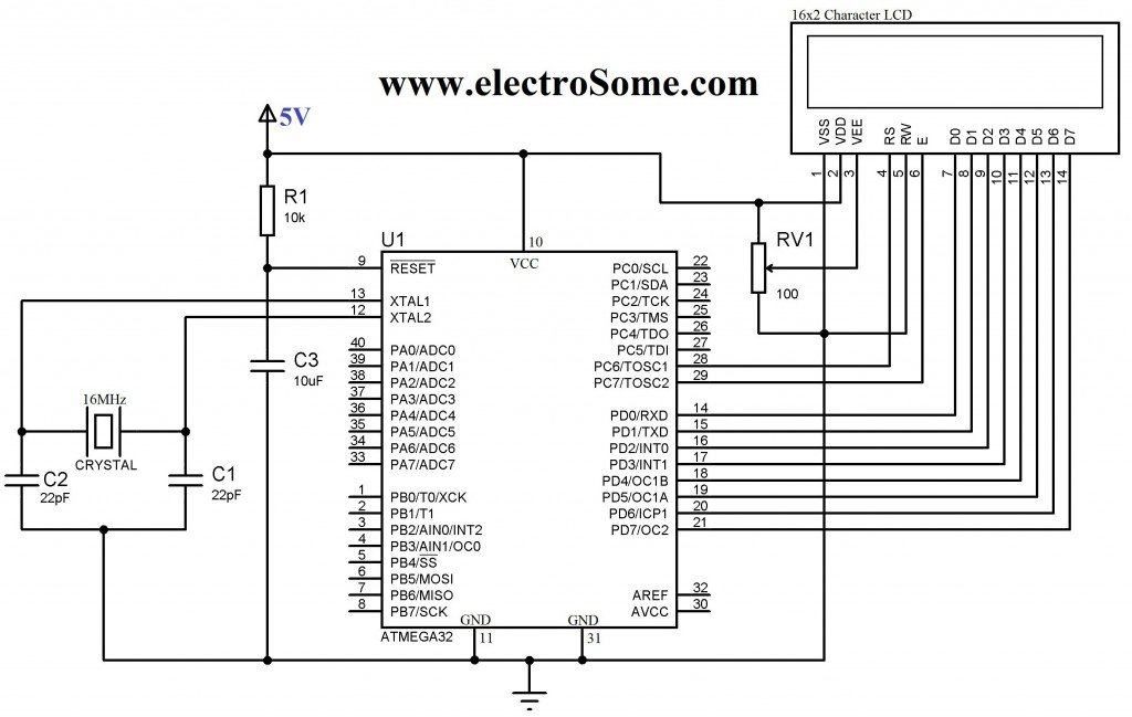
16×2 LCD can be interfaced with a microcontroller in 8 Bit or 4 Bit mode. These differs in how data and commands are send to LCD. In 8 Bit mode character data (as 8 bit ASCII) and LCD command are sent through the data lines D0 to D7. That is 8 bit data is send at a time and data strobe is given through E of the LCD.
But 4 Bit mode uses only 4 data lines D4 to D7. In this 8 bit data is divided into two parts and are sent sequentially through the data lines. The idea of 4 bit communication is introduced to save pins of microcontroller. 4 bit communication is bit slower than 8 bit but this speed difference has no significance as LCDs are slow speed devices. Thus 4 bit mode data transfer is most commonly used.
Function in lcd.h
Lcd8_Init() & Lcd4_Init() : These functions will initialize the 16×2 LCD module connected to the microcontroller pins defined by the following constants.
For 8 Bit Mode :
#define D0 eS_PORTD0
#define D1 eS_PORTD1
#define D2 eS_PORTD2
#define D3 eS_PORTD3
#define D4 eS_PORTD4
#define D5 eS_PORTD5
#define D6 eS_PORTD6
#define D7 eS_PORTD7
#define RS eS_PORTC6
#define EN eS_PORTC7
For 4 Bit Mode :
#define D4 eS_PORTD4
#define D5 eS_PORTD5
#define D6 eS_PORTD6
#define D7 eS_PORTD7
#define RS eS_PORTC6
#define EN eS_PORTC7
These connections must be defined for the proper working of the LCD library. Don’t forget to define these pins as Output.
Lcd8_Clear() & Lcd4_Clear() : Calling these functions will clear the 16×2 LCD display screen when interfaced with 8 bit and 4 bit mode respectively.
Lcd8_Set_Cursor() & Lcd4_Set_Cursor() : These function will set the cursor position on the LCD screen by specifying its row and column. By using these functions we can change the position of character and string displayed by the following functions.
Lcd8_Write_Char() & Lcd4_Write_Char() : These functions will write a single character to the LCD screen and the cursor position will be incremented by one.
Lcd8_Write_String() & Lcd8_Write_String() : These function will write string or text to the LCD screen and the cursor positon will be incremented by length of the string plus one.
Lcd8_Shift_Left() & Lcd4_Shift_Left() : This function will shift data in the LCD display without changing data in the display RAM.
Lcd8_Shift_Right() & Lcd8_Shift_Right() : This function will shift data in the LCD display without changing data in the display RAM.
8 Bit Mode Interfacing
Circuit Diagram
 For more detail: Interfacing LCD with Atmega32 Microcontroller using Atmel Studio
- What is the primary advantage of using 4 Bit mode for LCD interfacing?
4 bit mode uses only four data lines (D4 to D7) to save microcontroller pins. - How does 8 Bit mode send data to the LCD compared to 4 Bit mode?
In 8 Bit mode, 8 bit ASCII data and commands are sent simultaneously through data lines D0 to D7. - Which function initializes the LCD in 4 Bit mode?
The Lcd4_Init() function initializes the 16×2 LCD module connected in 4 Bit mode. - Can I use this library without built-in libraries in Atmel Studio?
Yes, the article states a custom LCD library was developed to solve the difficulty of no built-in libraries. - What happens when you call the Lcd8_Clear() function?
Calling this function clears the 16×2 LCD display screen when interfaced in 8 Bit mode. - How does the cursor position change after writing a string?
The cursor position increments by the length of the string plus one. - Does shifting data on the LCD affect the display RAM?
No, the shift functions move data on the display without changing the data in the display RAM. - What pixel matrix is used to display each character on this LCD?
Each character is displayed using a 5×7 or 5×10 pixel matrix.
