
Summary of Blinking LED using Atmega32 Microcontroller and Atmel Studio
This article guides users through blinking an LED using the Atmega32 microcontroller with Atmel Studio 6.0. It explains configuring Data Direction (DDR) and Port (PORT) registers, setting up a circuit with a 16 MHz crystal, capacitors, and resistors, and writing C code to toggle LEDs. The guide also covers bit manipulation techniques and Proteus simulation setup.
Parts used in the Blinking LED using Atmega32 project:
- Atmega32 Microcontroller
- LEDs
- Current limiting resistors
- 16 MHz crystal
- 22pF capacitors
- 10µF capacitor
- 10KΩ resistor
- PC2 pin for bit manipulation examples
Similar to printing ‘Hello World’ in C or C++, the very first step towards programming a microcontroller is Blinking a LED with a delay. Atmega32 is a very popular high performance 8 bit AVR Microcontroller. For this example project we need to use two registers DDR and PORT. DDR stands for Data Direction Register, it determines the direction (Input/Output) of each pins on the microcontroller. HIGH at DDR register makes corresponding pin Output while LOW at DDR register makes corresponding pin Input. PORT register is the output register which determines the status of each pin of a particular port. HIGH at PORT register makes corresponding pin Logic HIGH (5V) while LOW at PORT register makes corresponding pin Logic LOW (0V).
Getting Started with Atmel Studio 6.0
1. Download and Install Atmel Studio. You can download Atmel Studio from Atmel’s Website.
2. Open Atmel Studio
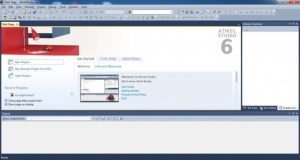
3. Select New Project
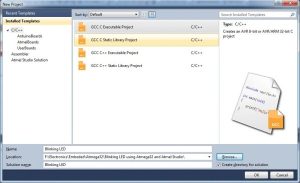
4. Select GCC C Executable Project, give a project name, solution name, location in which project is to be saved and click OK.
5. Selecting Microcontroller
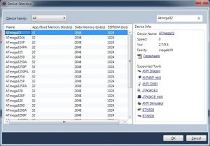
Choose the microcontroller that you are going to use, here we are using Atmega32. Then Click OK.
6. Enter the Program
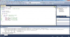
7. Then click on Build >> Build Solution or Press F7 to generate the hex file.
Circuit Diagram
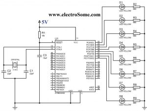
LEDs are connected to PORTC and current limiting resistors are used to limit current through them. 16 MHz crystal is used to provide clock for the Atmega32 microcontroller and 22pF capacitors are used to stabilize the operation of crystal. The 10µF capacitor and 10KΩ resistor is used to provide Power On Reset (POR) to the device. When the power is switched ON, voltage across capacitor will be zero so the device resets (since reset is active low), then the capacitor charges to VCC and the reset will be disabled. 30th pin (AVCC) of Atmega32 should be connected to VCC if you are using PORTA, since it is the supply voltage pin for PORT A.
Atmel Studio C Program
#ifndef F_CPU
#define F_CPU 16000000UL // 16 MHz clock speed
#endif
#include <avr/io.h>
#include <util/delay.h>
int main(void)
{
  DDRC = 0xFF; //Nakes PORTC as Output
  while(1) //infinite loop
  {
    PORTC = 0xFF; //Turns ON All LEDs
    _delay_ms(1000); //1 second delay
    PORTC= 0x00; //Turns OFF All LEDs
    _delay_ms(1000); //1 second delay
  }
}
- DDRC = 0xFF makes all pins on PORTC as output pins
- PORTC = 0xFF makes all pins on PORTC Logic High (5V)
- PORTC = 0x00 makes all pins on PORTC Logic Low (0V)
- _delay_ms(1000) provides 1000 milliseconds delay.
- while(1) makes an infinite loop
You have seen that PORT registers are used to write data to ports. Similarly to read data from ports PIN registers are used. It stand for Port Input Register. eg : PIND, PINB
You may like to set or reset individual pins of PORT or DDR registers or to know the status of a specific bit of PIN register. There registers are not bit addressable, so we can’t do it directly but we can do it through program. To make 3ed bit (PC2) of DDRC register low we can use DDRC &= ~(1<<PC2). (1<<PC2) generates the binary number 00000100, which is complemented 11111011 and ANDed with DDRC register, which makes the 3ed bit 0. Similarly DDRC |= (1<<PC2) can be used set the 3ed bit (PC2) of DDRC register and to read 3ed bit (PC2) we can use PINC & (1<<PC2). Similarly we can set or reset each bit of DDR or PORT registers and able to know the logic state of a particular bit of PIN register.
Proteus Simulation
If you haven’t yet started with PROTEUS, please go to this tutorial. Draw the above circuit in PROTEUS and make following setting on the properties of Atmega32.
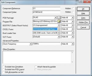
Don’t forget to set the clock frequency to 16 MHz.
You can download the Atmel Studio and Proteus files here…
Blinking LED using Atmega32 and Atmel Studio
- How do I determine if a microcontroller pin is input or output?
HIGH at the DDR register makes the corresponding pin Output while LOW at the DDR register makes it Input. - What function does the PORT register serve?
The PORT register determines the status of each pin, where HIGH sets Logic HIGH (5V) and LOW sets Logic LOW (0V). - Which software is required to program the Atmega32?
You need to download and install Atmel Studio 6.0 from the Atmel Website. - What components stabilize the operation of the 16 MHz crystal?
Two 22pF capacitors are used to stabilize the operation of the crystal. - How is the Power On Reset provided to the device?
A 10µF capacitor and a 10KΩ resistor are used to provide Power On Reset since the reset is active low. - What happens when voltage across the reset capacitor is zero?
The device resets because the reset is active low until the capacitor charges to VCC. - How do you make all pins on PORTC output pins in the code?
Setting DDRC = 0xFF makes all pins on PORTC as output pins. - Can individual bits of DDR or PORT registers be set directly?
No, these registers are not bit addressable, so you must use bitwise operations like AND or OR in the program. - What clock frequency must be set in Proteus properties for the Atmega32?
You must set the clock frequency to 16 MHz in the properties of the Atmega32. - Which register is used to read data from ports?
PIN registers such as PIND or PINB are used to read data from ports.
