Summary of Working with AVR microcontroller Communication Port Project
This article explains the history and technical specifications of the RS-232 (COM port) protocol, highlighting its transition from legacy UNIX systems to modern embedded microcontroller applications. It details voltage levels, data framing, and the necessity of voltage level shifters like the MAX-232 to interface with TTL logic. The text concludes by listing specific hardware and software tools required for a project involving AVR microcontrollers.
Parts used in the AVR Microcontroller Communication Port Project:
- AVRJazz Tiny2313 board
- Atmel AVR ATmega8 microcontroller
- Dallas Semiconductor MAX-232 chip
- WinAVR GNU C compiler
- Atmel AVR Studio 4 environment
- OspAvrII ver 5.47 Programmer
Back in the old days the COM port or known as RS-232 (EIA-232 standard) is one of the essential communications protocol and hardware use in many computer system installation start from small UNIX machine to the mainframe. The RS-232 protocol is used by terminal such as wyse60 or DEC vt100 which connected through direct cable or modem to the UNIX host or legacy system. Actually you could still tracked this history in the /etc/termcap file on many modern Linux distribution; later on I will use this table in our project for some terminal command’s information.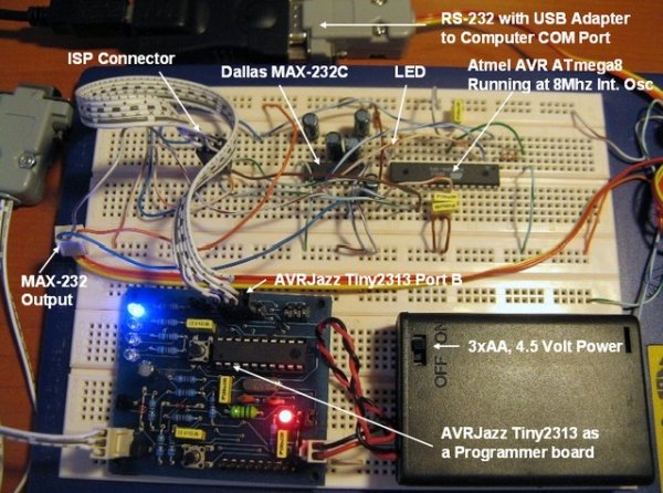
Back in the old days the COM port or known as RS-232 (EIA-232 standard) is one of the essential communications protocol and hardware use in many computer system installation start from small UNIX machine to the mainframe. The RS-232 protocol is used by terminal such as wyse60 or DEC vt100 which connected through direct cable or modem to the UNIX host or legacy system. Actually you could still tracked this history in the /etc/termcap file on many modern Linux distribution; later on I will use this table in our project for some terminal command’s information.
Today the used of this port is being replaced by the Ethernet protocol and hardware for connecting to the legacy system; most PC’s and notebooks nowadays has replaced this port with the USB (Universal Serial Bus). But in the embedded world the RS-232 communication protocol is still being used because of the reliability and simplicity. In the microcontroller’s world, we usually process just a small amount of data, therefore the RS-232 protocol is more than adequate to handle it.
The RS-232 devices will transmit or receive the data in the serial form and use the voltage level to differentiate between the logical “0” called Space (+3 Volt to +25 Volt) and the logical “1” called Mark (-25 Volt to -3 Volt) as seen from this following RS-232 voltage’s graph: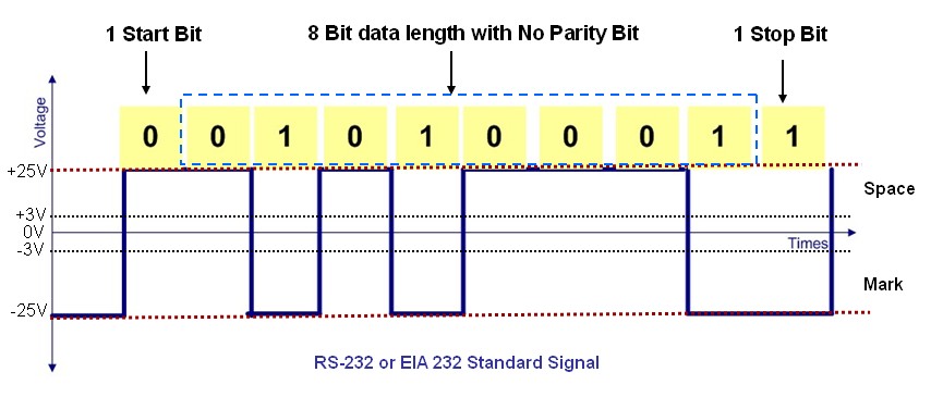
The voltage level between -3 Volt to +3 Volt relative to the ground is considered undetermined condition. Every data transmitted or received has the format form of start bit, data bit, parity bit and stop bit; the mostly used configuration with the microcontroller is 1 start bit, 8 data bit with no parity bit and 1 stop bit. The transmission speed is measured in BAUD RATE; which equal to the number of bit per second for the RS-232 device to transmit and receive the data. For example the speed of 19000 baud means 19000 bits can be transmitted and received for every second.
Because of the different voltage level between RS-232 and standard TTL/CMOS logic used in AVR microcontroller; therefore we use the voltage level shifter circuit to interface this two world. The following diagram is the commonly used circuit for this purpose; the first one use two transistors (Figure 1A) and the second one use the Dallas Semiconductor MAX-232 chip (Figure 1B):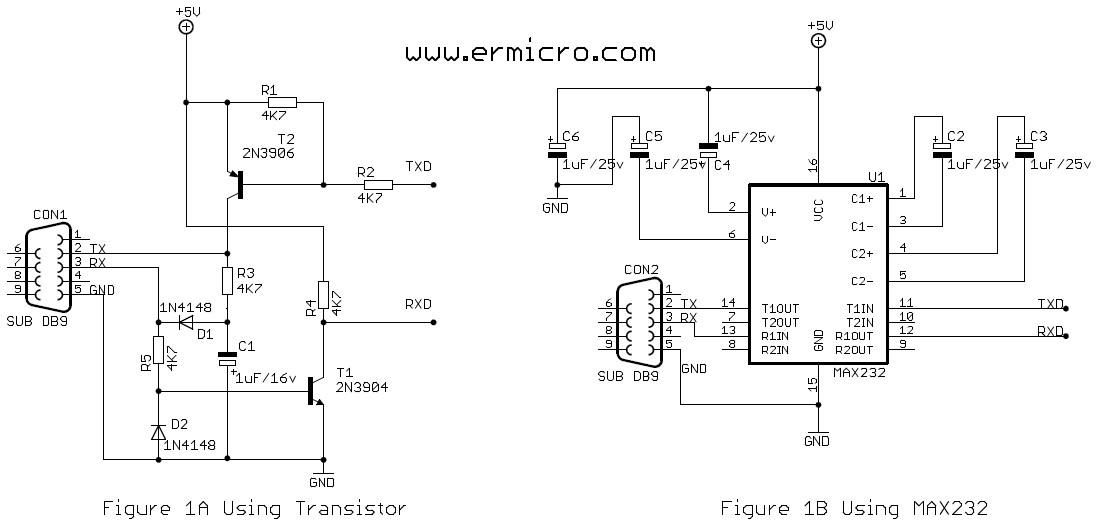
For the purpose of this project I will use this following hardware and software:
1. AVRJazz Tiny2313 board as the programmer board from ermicro
2. Atmel AVR ATmega8 for the target microcontroller
3. Dallas Semiconductor MAX-232 for the RS-232 voltage level shifter
4. WinAVR for the GNU’s C compiler
5. Atmel AVR Studio 4 for the coding, compiling and debugging environment
6. OspAvrII ver 5.47 Programmer from Mike Henning
For more detail: Working with AVR microcontroller Communication Port Project
- Why is RS-232 still used in the embedded world?
It remains popular due to its reliability and simplicity for processing small amounts of data. - What voltage levels represent logical 0 and 1 in RS-232?
Logical 0 (Space) uses +3 to +25 Volts, while Logical 1 (Mark) uses -25 to -3 Volts. - What happens if the voltage is between -3 and +3 volts?
This range is considered an undetermined condition relative to the ground. - What is the standard data format configuration for microcontrollers?
The most common setup includes 1 start bit, 8 data bits, no parity bit, and 1 stop bit. - How is transmission speed measured in RS-232 devices?
Speed is measured in BAUD RATE, representing the number of bits transmitted per second. - Why is a voltage level shifter circuit necessary?
A shifter is needed because RS-232 voltage levels differ from the standard TTL/CMOS logic used in AVR microcontrollers. - What are the two common circuits used for voltage level shifting?
The first uses two transistors, and the second uses the Dallas Semiconductor MAX-232 chip. - Which file on Linux distributions contains terminal command history?
The /etc/termcap file tracks this history on many modern Linux distributions.