Summary of MIDI synthesizer Using Atmega32
The ECE 476 final project involved building a MIDI synthesizer using an ATmega32 microcontroller. The system decodes MIDI packets from a FATAR Studio 610 plus keyboard via an optoisolator and UART interface. The microcontroller processes the data to generate 8-bit sine waves, which are converted to analog signals through a DAC and filtered before being sent to TV speakers for audio output.
Parts used in the MIDI Synthesizer:
- MEGA 32 microcontroller
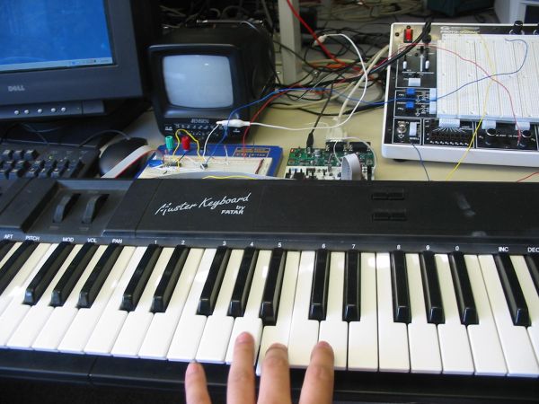
- FATAR Studio 610 plus keyboard
- Optoisolator
- UART interface
- DAC (Digital-to-Analog Converter)
- Low-pass filter
- TV-speaker
Introduction:
MIDI Synthesizer
Our Final Project for ECE 476 was building a MIDI synthesizer using a MEGA 32 microcontroller. At first we wanted to tear apart an old keyboard and use the MCU to decode directly from the sensors which detected key presses. We then learned about the MIDI protocol and decided to use the MCU to decode MIDI packets sent by they keyboard and then play the appropriate note.
Once we determined which note the keyboard is trying to play, we are then able to synthesize the correct 8-bit sine wave. We then wanted to be able to send the output of our signal to speakers so we could hear the results.
This project was a great learning experience about how music is replicated digitally and also taught us a great deal about signal sampling and generation.
Design
Project Idea
Our first idea for this project was to take an old keyboard and rewire it to use the microcontroller to generate sound to our own set of speakers. Our TA then suggested we decode the output of a MIDI keyboard and produce an appropriate sound. Our project is specifically designed for the Studio 610 plus keyboard by FATAR. This was the only MIDI device we had access to so we could not make our MIDI decoding scheme any more general. Our synthesizer is not guaranteed to work unless it is hooked up to this specific keyboard.

Project Structure
The overall setup of our project goes like this:
Keyboard Press —-> MiDI output —-> optoisolator —-> UART —-> code to pick correct note —-> DAC —-> low-pass filter —-> TV-speaker.
For more detail: MIDI synthesizer
- What was the initial idea for the project?
The team initially planned to tear apart an old keyboard and use the MCU to decode directly from the sensors detecting key presses. - Which specific keyboard does the synthesizer support?
The project is specifically designed for the FATAR Studio 610 plus keyboard. - How is the sound signal generated after decoding the note?
The system synthesizes the correct 8-bit sine wave based on the determined note. - What component isolates the MIDI output from the microcontroller?
An optoisolator is used between the MIDI output and the UART interface. - What type of waveform is produced by the synthesizer?
The synthesizer produces an 8-bit sine wave. - How is the digital signal converted to analog for the speaker?
A DAC converts the signal, followed by a low-pass filter before reaching the TV-speaker. - Why was the design limited to one specific keyboard?
The MIDI decoding scheme could not be made more general because the FATAR Studio 610 plus was the only MIDI device available. - What learning outcomes did this project provide?
The project taught how music is replicated digitally and provided experience with signal sampling and generation.