Summary of Morse It!
This project details the construction of a DIY Morse code communication system using 3-key transmitters and LCD receivers. The author built a transmitter with hook switches to send dots, dashes, and spaces via RF modules, paired with an Atmega8-based receiver that decodes signals and displays messages on an LCD screen. The guide covers circuit assembly, component sourcing, and AVR microcontroller programming for long-distance room-to-room messaging.
Parts used in the Morse Code Communication System:
- Perfboard
- Hook switches (3 units)
- Wires
- Transmitter module with antenna
- Plastic box for enclosure
- 9v battery
- On/off switch
- Atmega 8 microcontroller
- 28 Pin IC socket
- Capacitors (1000uf, 10uf, 0.1uf, 0.01uf)
- 7805 voltage regulator
- Red LED
- DC Power jack
- Push button
- Receiver module
- 16x2 LCD
- Trimmer pot 10k
- Male and Female header pins
- HT12E encoder IC
- HT12D decoder IC
Before cell phones even before telephones, people communicated through Morse code. Despite being a technology that is over 160 years old, it’s still used today among amateur radio users and on some ships. While you might not find any particular use for Morse code in your daily life, learning Morse is a fun and engaging hobby.
I made this just for fun and it was also very fascinating for me that you can communicate with anycome or talk with anyone just by dots and dash and in this case by just 3 keys.
The first switch is for Dot,the second is for Dash and the third is for Enter/Space and if you write a wrong code then the screen says Invalid!
The main purpose of this project is to practice morse code and also you can send messages to another person sitting in other room.
Enjoy!
Step 1: Materials Required:
Electronics parts:
1)For transmitter circuit:
-Perfboard x1
-3 x hook switches
-Wires
-Transmitter module
-plastic box for enclosing the circuit
-9v battery
-on/off switch
2)For Reciever Circuit:
–Perfboard x 2
-Atmega 8 x 1
-28 Pin IC socket for Atmega 8 x 1
-1000uf capacitor x 1 and 10uf capacitor x 1
-0.1uf ceramic capacitor x 1
-0.01uf ceramic capacitor x 1
-7805 voltage regulator x 1
-Led(Red) x 1
-DC Power jack x 1
-Push button x 1
-on/off switch
-Reciver module
-16×2 lcd
-trimmer pot 10k
-Male and Female header pins
-Plastic box for enclosing the circuit
Step 2: Making the Transmitter Hook Switch Circuit:
Lets get started with the Project!
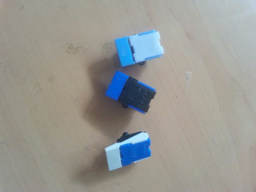
-I used Hook switches salvaged from old non working telephone sets in making the transmitter switch circuit.One can also use spst push buttons but I like the way these hook switches make a click sound when pressed and they can be easily mounted on a perfboard!
-Now,mount the hook switches on the perfboard as shown in the image.
-A hook switch has 6 pins and its internal structure is different from regular switches and push buttons, So With the help of a multimeter check the continuity of the switch.
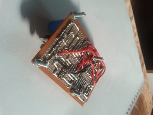
-After a few minutes of tinkering with the switch I was able to figure out how the pins were connected and I soldered the pins together that were connected internally(Shown in image).
-Each hook switch will work like an spst push button which connects two points in a circuit when it is pressed.so the one end of the switch is connected to the ground and the other end connected to a pin of encoder IC(covered in next step).
-Now solder together all the ends of the hook switches that will be connected to the ground(shown in image).
-After this take a small lenght of wire and solder it to the other end of the switch(shown in figure),repeat this for other two switches.
Step 3: Transmitter Module:
-Buy the transmitter module from Amazon or ebay and make sure that the transmitter module has a antenna mounted on it.
-I made my own transmitter circuit and i got my antenna from an old radio.
Step 4: Finishing the Transmitter Circuit:
1) In the previous step we constructed the Hook switch circuit and now its time to connect the switch circuit to the transmitter module
2) connect the first wire coming from switch 1 to the pin 12 of ht12e ic.
connect the second wire coming from switch 2 to the pin 11 of the ht12e ic.
connect the third wire coming from switch 3 to the pin 10 of the ht12e ic.
3) After this connect the ground wire from the switch circuit to the ground of the transmitter module( note that the ground of the switch circuit and that of transmitter module should be same.)
4) Power the transmitter module with the help of a 9v battery( NOTE-do not power the transmitter module directly with a 9v battery,make sure the transmitter module you buy has a 7805 voltage regulator in it so the circuit gets 5v only.)
5) Attach a switch to on and off the circuit
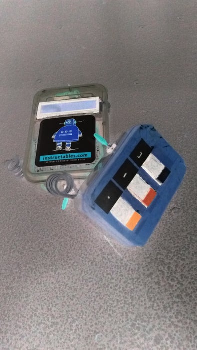
6) After this pack all of it inside a small plastic box…like i did!!
P.S- I made my own transmitter module so i connected the wires coming from the switch circuit directly to the pins of the ht12e ic but the module you buy online comes with male header pins connected to the ic pins so you need to do a little tinkering and soldering to complete the circuit or you can do the connections with the help of jumper wires.
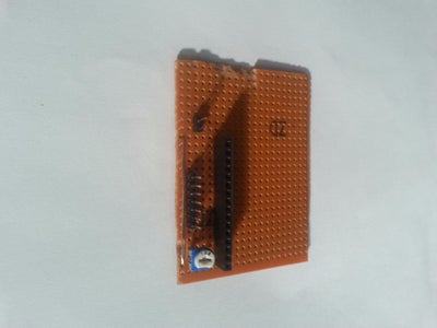
Step 5: Atmega 8 Board:
-You can either make your own Atmega 8 board or you can buy it from amazon or ebay, its quite cheap!
-I made this board a long time ago so i didn’t had to buy a new one and if you dont want to purchase and make your own then i have provided the schematic in the above images.
Step 6: Making the Lcd Module:
–Make the lcd module and connect it to the Atmega 8 board as shown in schematic.
Note-The ground of lcd module and atmega board should be same.
Step 7: Reciever Module:
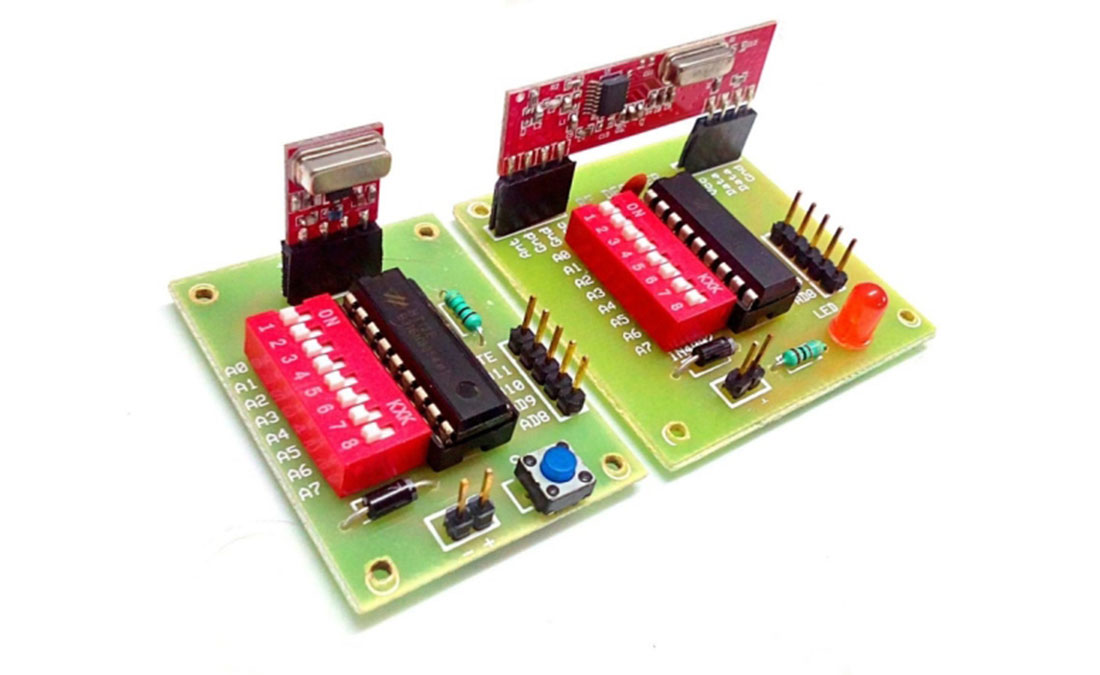
-We need to use only 3 pins of reciver module ie pin 10,11 and 12 of ht12d ic
– Connect pin PC0 of Atmega 8 board to pin 10 of HT12D IC.
Connect pin PC1 of Atmega 8 board to pin 11 of HT12D IC.
Connect pin PC2 of Atmega 8 board to pin 12 of HT12D IC.
-To power the reciver module connect a wire from the 5v supply of the atmega board ( Most of the modules or boards have separate male header pins for 5v supply and ground ) to the input header pin of the reciever module The input for reciver module should be 5v only
-Connect a wire from the Ground of the atmega board to the ground pin of the reciever module
NOTE –
-The ground of the Atmega 8 board and the reciver module should be common.
-Buy only those reciver modules which have 7805 5v voltage regulator in them.
Step 8: Finishing the Reciever Circuit:
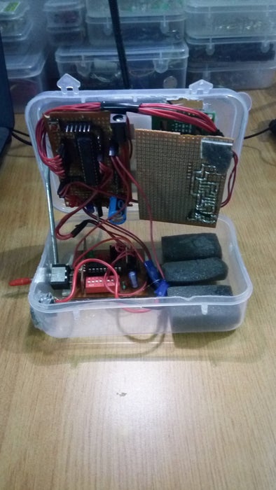
-After connecting the atmega board,reciver module and the lcd module together,put them in a box.
-Make sure the ground of the atmega board,reciver module and the lcd module is common(same ground).
-I didnt had an li-ion battery nor did i had any space in the box for them so i powered the circuit with the help of an dc adapter.
Step 9: Coding:
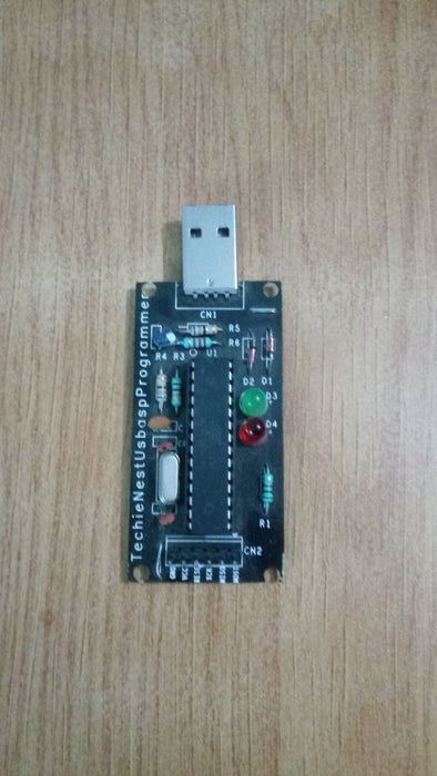
-coding done in AVR studio
-connect one end of the ribbon cable to the usb programmer and the other to programming pins on the atmega board.
-Burn the program using AVRDUDE.
-I am assuming that you know how to program avr atmega microcontrollers so not going into detail.
Step 10: Finish!
Source: Morse It!
- How do I create the input interface for the transmitter?
You use three hook switches salvaged from old telephones, where the first is for Dot, the second for Dash, and the third for Enter or Space. - What happens if I enter an incorrect code?
The screen on the receiver will display Invalid when a wrong code is written. - Can I power the transmitter module directly with a 9v battery?
No, you must ensure the module has a 7805 voltage regulator so it receives only 5v, or you risk damaging the circuit. - Which pins connect the switch circuit to the HT12E IC?
Switch 1 connects to pin 12, Switch 2 to pin 11, and Switch 3 to pin 10 of the HT12E IC. - How do I power the receiver module?
You should connect a wire from the 5v supply of the Atmega board to the input header pin of the receiver module. - What are the required connections between the Atmega 8 and the HT12D IC?
Connect PC0 to pin 10, PC1 to pin 11, and PC2 to pin 12 of the HT12D IC. - Is it necessary to have a common ground across all components?
Yes, the ground of the Atmega board, receiver module, and LCD module must be common to function correctly. - What software was used to write the code for this project?
The coding was done using AVR Studio. - How do I burn the program onto the microcontroller?
Connect a USB programmer to the programming pins on the Atmega board and burn the program using AVRDUDE. - Can I use push buttons instead of hook switches?
Yes, you can use SPST push buttons, though the author prefers hook switches for their click sound.