Summary of NeoPixel Reactive Table
Welcome to my version of the LED reactive table! I was inspired by earlier discrete-LED projects but used NeoPixels for easier, colorful effects. The table uses an array of IR emitters and photodiode sensors to detect object location; an ESP32 reads multiplexed sensor values and drives 61 NeoPixel rings (12 LEDs each) arranged in a hexagonal grid. The build covers cell construction, hole jigs, wiring emitters/sensors, multiplexers, LED chaining/power distribution, ESP32 wiring, and software (FastLED) with pattern examples and mapping details.
Parts used in the NeoPixel Reactive Table:
- Black cardboard or foam core sheet (~18 x 30 in)
- 940nm IR LEDs (approx. 156)
- 940nm IR photodiodes (approx. 61)
- Resistors 6.8–12 ohm (approx. 52)
- 10K ohm resistors (61)
- 12-pixel WS2812 / WS2811 LED rings (61)
- Female-female three-wire jumpers (10cm, ~50)
- Dupont connector kit and crimping tool
- Analog multiplexer boards based on CD74HC4067 (4)
- 5V 20A power supply
- ESP32 microcontroller
- 22AWG or 24AWG bare copper wire / bus bar wire
- 22AWG or 24AWG silicone coated hookup wire (various colors)
- 18AWG or 20AWG hookup wire (red and black for power)
- 28AWG hookup wire for sensors
- Prototyping boards / perfboard
- Right-angle header (2-pin and 3-pin pieces)
- Kapton tape
- 1000uF coupling capacitor
- Soldering tools and general soldering supplies
Welcome to my version of the LED reactive table! I was inspired by previous work using discrete LEDs, such as this one, but I figured it would be easier and more fun to use NeoPixels — programmable RGB LEDs that can be set to any color you want. The table consists of a large array of infrared emitters and sensors, which are used to detect the rough location of objects on or above the table. This data is fed into a microcontroller that lights up the NeoPixels in interesting patterns. Check out some of the examples in the videos above.
Now, I’m not going to lie to you: this project is a lot of work, and some of it is pretty tedious. But there are a lot of useful techniques and components that you could use for other kinds of projects. The design is also fairly modular, so you can make it as big or small as you like. Don’t be intimidated by the number of steps — I just broke the process into a lot of small, detailed steps.
There are five main components of the table:
(1) IR emitters — an array of simple IR LEDs that cover the surface of the table creating a uniform field of infrared illumination. These LEDs are all wired together and are on all the time (although the light is not visible to the naked eye).
(2) IR sensors — an array of IR photodiodes, wired separately so that we read the voltage on each one individually. When infrared light from the emitters is reflected back by some object (your hand, e.g.), the photodiodes allow current to flow through them, which we can measure. The voltage varies according to the strength of the reflected light.
(3) Sensor multiplexer — a set of analog multiplexer boards that allow us to read any of the IR sensor values. We will need four boards for this version of the project, since it has a lot of sensors.
(4) NeoPixels — each sensor has a group of neopixels (also known as WS2811/WS2812 RGB LEDs) associated with it; the value of the sensor is rendered visually on them. In my version, each unit consists of one IR sensor and a ring of 12 pixels — in the code, I refer to this unit as a “cell”.
(5) Microcontroller — the microcontroller runs the code that repeatedly reads all of the sensor values and renders the visual effects on the LED pixels. I provide the code for my animations later in the Instructable — feel free to copy and modify to your liking. I use the FastLED library to drive the NeoPixels.
My version of the table has 61 cells — that is, 61 IR sensors and 61 LED rings — organized in a hexagonal grid. I will show you how to lay out the grid and the LEDs in this arrangement, but there are many other ways it could be done. And again, you can make a table with as many or as few cells as you want.
You will need the following skills to complete this project: soldering (there is a lot of soldering to do), basic wiring, some Arduino programming, attention to detail, and tons of patience!
Step 1: Materials
Below you will find exact counts of the materials you will need. The total cost of the materials will vary depending on where you buy them, but the LED rings are the most expensive component, and will probably set you back at least $100. I strongly recommend buying extras of almost everything — parts inevitably get lost, damaged, or are defective.
(1 sheet) Black cardboard or foam core, roughly 18 inches by 30 inches (you can always trim it down later). You can use other materials, but make sure that it is relatively easy to punch holes through it for the electronic components.
(156) IR emitters: 940nm wavelength IR LEDs. You will need 156 of them, but get more; they are cheap. I bought these.
(61) IR photodiodes: make sure they detect 940nm IR. You will need 61, but get extras. For example, these ones
(52) resistors in the range 6.8 ohms to 12 ohms. The exact value depends on the voltage rating of the IR emitters you buy. We will be powering groups of three in series with 5V input voltage. You can use this calculator to estimate the size of the resistor you’ll need.
(61) 10K ohm resistors; one for each IR photodiode. These serve as pull-up resistors.
(61) 12 pixel WS2812 rings — I bought mine from AliExpress (e.g., these) because they are cheap, but they take a while to get in the mail.
(50) 10cm three-wire female-female jumpers — like these.
A Dupont connector kit like this. I also recommend getting the crimping tool.
(4) Analog multiplexer boards — I bought these ones
(1) 5V 20 amp power supply — I bought this one
(1) ESP32 microcontroller — the ESP32 is an amazing microcontroller, with tons of memory and processing power, which you’ll need for this project. You can get them on Amazon (e.g., here), but AliExpress has more choices for less money if you’re willing to wait to get them (I bought this one).
You will also need a variety of hookup wires and prototyping boards to hold the components:
22AWG or 24AWG bare copper wire or bus bar wire. Get a decent size spool.
22AWG or 24AWG hookup wire. I like the silicone coated stuff because it is so flexible and heat resistant. Get a few spools of different colors.
18AWG or 20AWG hookup wire in black and red for power
28AWG hookup wire for the sensors — you’ll need a lot because there is a separate wire for each of the 61 sensors.
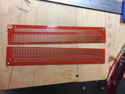
Prototyping boards like these.
Step 2: Building a Single “cell”
Before we get to building the full table surface, I’ll show you how to make a single “cell”: a set of IR emitters, a single IR sensor, and an RGB LED ring. In some sense, the table design is simple: it is just a large array of these cells.
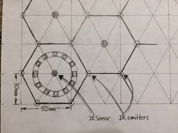
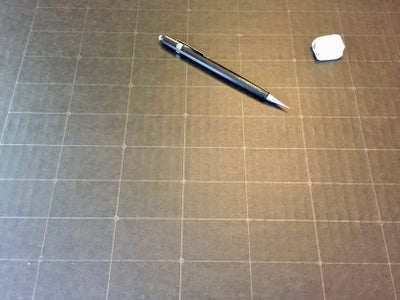
In the first photo you’ll see a drawing of the layout. I organized my cells as interlocking hexagons, and in later steps I’ll show you how to lay them out on the cardboard surface. For now, we’ll just look at how a single cell is built, so the exact layout is not important.
The IR emitters sit at the intersection of each hexagon edge; the IR sensor is in the middle, surrounded by the LED ring. The second photo shows the layout on the cardboard (I actually drew two cells, but I’ll only wire one of them).
Step 3: Punch Holes for the IR Sensors and Emitters
The electronic components of the table sit on the top surface of the cardboard, but the wiring is all on the back. To make this possible we punch holes through the cardboard in the desired pattern. In order to make the components fit I built two hole punching “jigs” that ensure proper spacing of the holes.
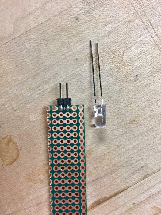
The first jig is for the IR emitters and sensors. I soldered a two-pin piece of right angle header onto a small protoboard (see photo 1). The spacing of the holes exactly matches the spacing of the LED leads. You can add some hot glue and sharpen the points to make it easier to punch through the cardboard.
Start by punching holes for the emitters at each corner of the hexagon (see photos 2-4). Notice that the holes are aligned horizontally — this will be important for wiring on the back.
Next punch the holes for the emitter in the middle — notice that these holes are aligned vertically. See photo 5. When you’re done, you should have the pattern shown in the last photo.
Step 4: Punch Holes for the RGB LED Ring
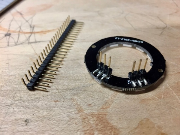
Each RGB LED ring has six pads on the back (see first photo) — three are inputs and three are outputs, which makes them easy to chain together. My strategy for attaching these rings to the board is to solder a three-pin piece of right angle header to each set of pads, then push these pins through the cardboard, and link them together on the back with three-wire hookup.
To punch the holes for the ring I made another jig, which is just a ring with the pins soldered on and sharpened. You can add some hot glue to make the set up stronger, so it doesn’t break under the strain. I also glued on two pieces of thin wire to provide a “cross hair” for aligning the ring. See photos 2-4.
Line up the cross hairs with the center of the ring and push the pins through to create the six-hole pattern (photo 5). The final result should look like photo 6. Notice how the pins of the LED ring line up to the side of the center — this is crucial to the wiring on the back.
Step 5: Insert the IR Emitters and Sensor
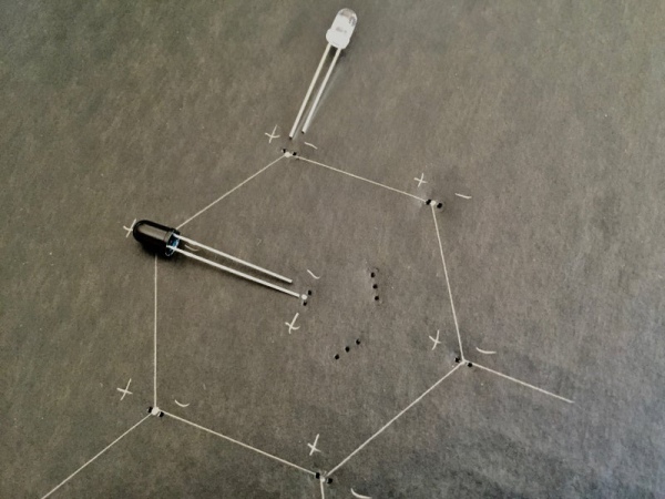
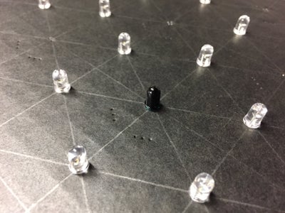
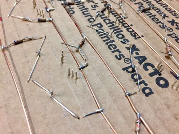
Get a bunch of IR emitters (the clear IR LEDs) and one IR sensor (the dark one) for each cell. To simplify the wiring, and keep myself from making mistakes, I have all the IR LEDs oriented the same way with respect to their polarity. For the emitters all of the positive leads (the longer ones) are on the left, and all the negative leads (the shorter ones) are on the right. For the sensors the positive lead is on the bottom and negative lead is on the top. See the first photo.
Push all the LEDs through the holes. They should fit snugly. You may need to wiggle them a bit to find the hole through the back side of the cardboard. It should look like photo 2 when done.
Flip the board over — you should see the leads poking through, with all of the positive ones (the longer ones) oriented the same way.
Step 6: Wire Together the IR Emitters
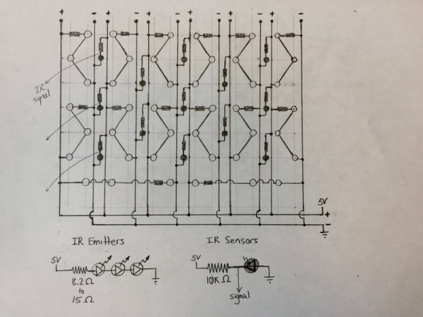
The first photo above shows the overall circuit design for the IR emitters and sensors. I’ll first show you how to wire one of the cells, then show how to scale it up for the whole table. The main idea is to run a series of positive and negative “rails” across the bottom of the table to make it easy to wire them all together.
Typical IR emitters are rated for 1.2V to 1.5V. Since we will be powering our table with 5V power, we need to account for this difference. The easiest strategy is to wire three in series at a time, then add a small current-limiting resistor just to protect them. The second photo shows the IR emitter circuit.
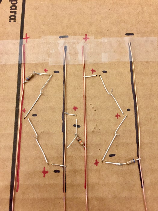
On the back of the cardboard you can draw lines to show where the power rails will be. They arranged in pairs — a pair to the left of the IR sensor, and a pair to the right of the sensor (see photo 3 — the black line all the way to the left was already there).
Next, add the power rails. I used 22 AWG bare copper wire segments. Lay them in rows following the red and black lines.
Start folding the leads down as shown in photo 4: fold the first positive lead so it crosses the positive power rail; then fold the negative lead towards the positive lead of the LED below it. Continue folding, matching positive to negative to form a series chain, ending with the last negative lead crossing the negative power rail. When you’re done, it should look like photo 5.
Add a resistor (should be somewhere in the range of 6.8 ohm to 12 ohm, depending on your IR emitters). Make sure the resistor is in series with the three IR emitters. See photo 6.
Twist all the leads together and trim the extra as shown in photos 7 and 8. In the full-scale table, the next step would be to solder all the connections.
Step 7: Wire the IR Sensor (photodiode)
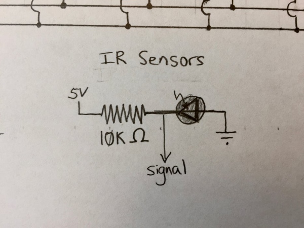
The IR sensor is a photodiode that works in an unusual way called reverse bias: the positive lead (the longer one) is connected to the negative power rail; the negative lead is connected to the positive power rail. As you might expect, this blocks the current — unless there is infrared light shining on it, in which case it allows the current to flow (in the opposite direction from a regular LED!) You can find more information here, and one many other web sites.
The circuit diagram is shown in the first photo. Two important things to note: first, we read the signal out on the positive side, which means that the pin will read high (5V) when there is no IR light shining on it (no object in front of it). We add a 10K ohm resistor between the 5V power and the signal to serve as a pull-up and to protect the circuit. When IR light shines on the photodiode, it loses its resistance, and all the current flows directly from power to ground, cause the signal pin to read low (close to 0V).
Fold the positive lead so that it crosses the negative power rail. Fold the negate lead straight down (see photo 2). Add the 10K ohm resistor to connect the negative lead to the positive power rail. Leave a little segment of the lead sticking out — this is where we will attach the wire to read the signal. Crimp and trim all the wires. See photo 3.
Step 8: Complete IR Emitter and Sensor Cell
Repeat the earlier steps to complete the second series of IR emitters on the right side. Pay close attention to the polarity of the LEDs and the power rails. Don’t forget the current limiting resistor! The final circuit should look like the photo above.
Another important thing to notice: the 6 pin holes for the RGB LED should not be in the way or cross any of the wires you have in place.
Step 9: Add the RGB Ring
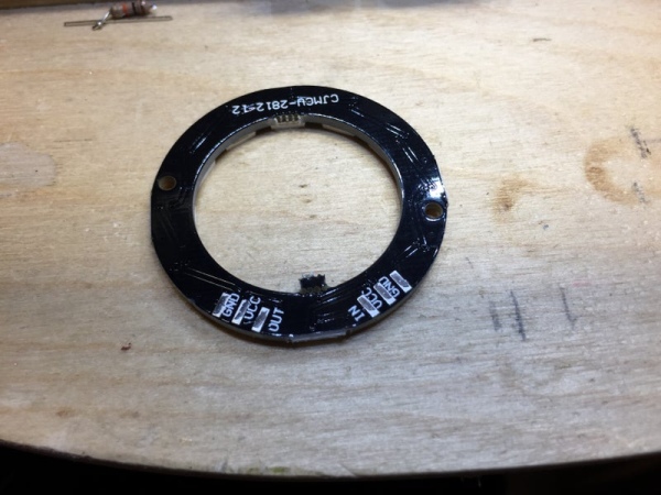
Prepare an RGB LED ring by solder two three-pin segments of right angle header onto the pads. My strategy is to add a dab of solder to two of the pads (see the second photo), then “glue” the segments on just using those two pads. Once secure, go back a complete the solder joints on all six pads.
Use tweezers to remove the black plastic holding the pins together (see photo 5). Be careful not to pull the pins off or break the solder!
Push the 6 pins through the holes as shown in photos 6 and 7. Flip the board over — you should see the 6 pins poking through, with plenty of extra lead. In photo 8 you’ll see how the pads line up: the ground pins are always the outside pins, the power pins are the middle, and the signal pins are the inside.
Ultimately, we will join all the rings together with three-pin connectors (see last photo). I chose connectors with colors that match the pins (black and red for power, white for signal).
Step 10: Scaling Up
Now that you know how a single cell is constructed, you can move on to building a full-size board. In some ways, it is simple: just repeat the cell pattern as many times as you like. I chose a pattern with 61 cells, which makes it both symmetric and results in nice even numbers of components. I’ll show you how to build this configuration.
Step 11: Full Grid Layout
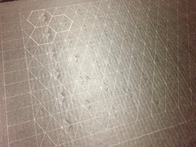
The first step is to lay out the hexagonal grid on the top of the cardboard sheet. There are some crazy web pages about hexagonal grids, but I came up with my own scheme for drawing one. First, draw a 50mm by 30mm grid (first photo). Every other intersection (photo 2) will become the center of a “cell” where a single IR sensor sits. Connecting these points with a series of diagonals gives the outline of the hexagons (see photos 3-5). The last photo shows the final product. You don’t need to outline the hexagons, but I found it helpful to remind me where everything goes.
Step 12: Punch Holes for the Components
Using the technique from Steps 3 and 4, punch holes for the IR emitters and sensors, and the RGB LED rings. Remember: the corners of the hexagons are the IR emitters, and the holes should be oriented horizontally; the centers of the hexagons are the sensors, and the holes should be oriented vertically. The 6-hole punch for the RGB LED ring should run either to the left or right of the sensor. See photos.
Step 13: Add All of the IR Emitters and Sensors
Start by pushing IR emitters through all of the horizontal holes at the corners of the hexagons. You should be able to clearly see the hexagonal grid shape (see first photo). IMPORTANT: Make sure all the positive leads are facing the same way, as we did in Step 6.
Next, push all the IR sensors (photodiodes) through, again paying close attention to the polarity, so that they are all consistent. The result should look like photo 3. At this point, you will have a lot of pointy leads sticking out the bottom of the cardboard, so be careful.
Step 14: Fold Down the Leads
Carefully fold down all of the leads, as demonstrated in Steps 6 and 7. For the IR emitters, remember that you are trying to form groups of three LEDs in series that go from the positive power rail to the negative power rail. Any errors here will result in either a dark spot in your LED array, or a short circuit.
Twist together the pairs of LED leads (photo 4).
Step 15: Add the Power Rails and Connect the Components
Lay down the power rails in pairs, as shown in Step 6. In my design, there are 12 pairs of power rails. Make sure they cross over the leads that are folded — this will make crimping them easier.
Fold the wires over power rails and crimp them (see photo 2). Make sure to leave one side of each circuit open for the resistor (see photo 3).
Add the resistors (both the current limiting ones for the emitters and the pull-up resistors for the sensors). Crimp and trim all connections (photos 4-6).
IMPORTANT: Notice that at the bottom I have a row of IR emitters left over (i.e., they don’t fit into the groups of three). To make sure they are lit, I made horizontal groups of three, which need to cross the power rails. I used Kapton tape to keep them insulated.
Solder all the joints — yes, it’s a lot of soldering! You can see the final product in photos 7.
Step 16: Test 1: Check IR Emitter Groups
At this point, you can test the IR emitters in vertical groups. Attach 5V power to a pair of copper rails. One problem: you can’t see the IR light! It turns out, though, that most point-and-shoot cameras detect IR light and show it as purple. Shut off the lights, and point your camera at the LEDs. I tried to take some photos (see above).
If any individual LEDs don’t light up, it probably means they are defective. If a group of three LEDs in a single series circuit doesn’t light up then either one is defective, or one of them is turned the wrong way (wrong polarity). You can use a multimeter to check. Pull out and replace LEDs as necessary.
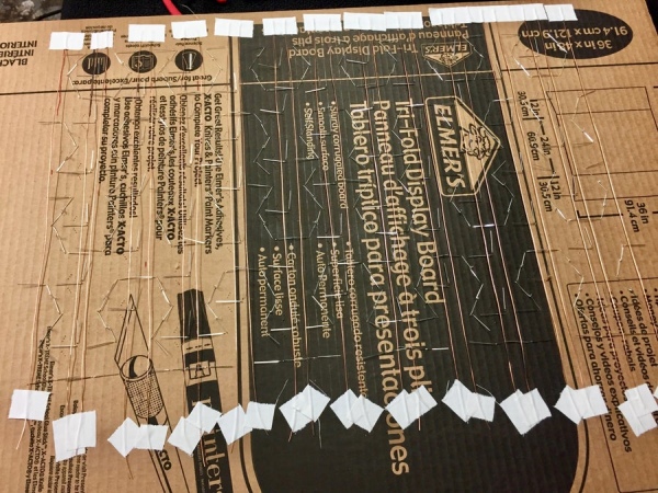
Step 17: Tie Together the Individual Power Rails, and Test
We need an easy way to power all those positive and negative power rails. My technique is to take a section of hookup wire (22 or 24 AWG) solder each power rail to a different point along the wire.
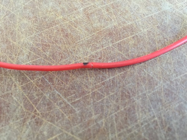
Start by laying out the hookup wire and marking the places to connect the rails. Remember, all the positive rails should connect to the positive power line; all the negative (ground) wires to another. Using a wire stripper, gently carve out a section of the insulation and remove it with an Exacto knife. See photos 1 to 3.
In photos 4 and 5 you’ll see all of the positive rails soldered to the red wire, and all the negative rails soldered to the black wire.
Now test all the emitters! Connect your 5V power supply to the red and black hookup wires. Get your point-and-shoot camera and check it out in the dark.
Step 18: Test the IR Sensors
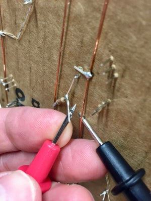
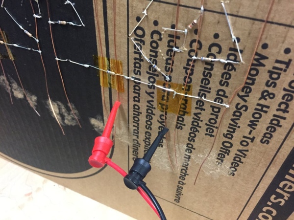
At this point you can test the IR sensors by hooking up power and measuring the voltage across the diode. Attach the probes from your multimeter to the signal pin (the extra lead sticking out between the photodiode and the resistor) and on the negative (ground) wire (see first photo). With power on the voltage should read something in the 3V to 5V range.
Next, wave your hand in front of the sensor (photo 2). The voltage should now read something close to zero (my multimeter is showing 170 millivolts in photo 4).
You can test each of the sensors, but this job is extremely tedious. Test a few, and then we’ll test them all when the multiplexer and microcontroller are added.
Step 19: Multiplexing the IR Inputs
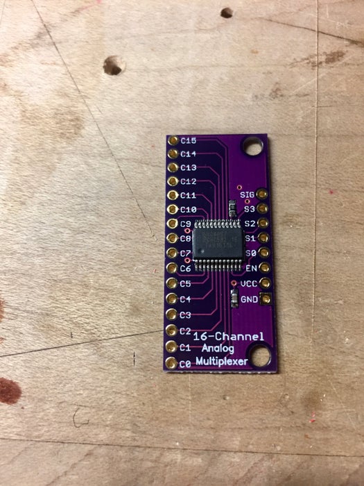
One of the challenges in this project is the number of inputs. There are 61 IR sensors — too many to attach each one individually to a pin on a microcontroller. Instead, we use an analog multiplexer. In this case, I chose one based on the CD74HC4067 chip, which can handle 16 inputs, so we’ll need four of them to handle 61 inputs. The first photo shows one of the boards.
Each multiplexer has four digital “selector” inputs and one signal output. Each digital pin can either be set high or low, allowing for 16 combinations. Setting a particular pattern selects which input to channel to the signal output — specifically, the binary encoding of the input we want. For example, to read input number 13, we would set the selector pins to high, high, low, high — 1101, the binary encoding for 13. Reading the signal output will give us the same reading as analog input number 13.
There are a number of ways to combine multiplexers to handle more inputs. My strategy is simple: wire all of the digital selector lines together (so all four multiplexers get the same input selector), but then connect each signal output to a separate microcontroller pin. To read an arbitrary input (out of the 61), we take the low four bits of the input number and write it out to the selector pins; then we use the next two bits to decide which signal input to read. The code I provide later has all of this logic in it.
Step 20: Building the Multiplexer Unit
The four multiplexer boards are assembled on a full-sized protoboard cut in half. Photos 1 to 3 show the setup. The sixteen inputs of each board are on the left side. I add right-angle male-female header all the way down to allow the IR input wires to be plugged and unplugged. You could just solder them in, but I wanted to make it repairable if necessary. Next, use regular header to solder the multiplexer boards onto the big board (photo 5). Add wires for power and ground for each board (photo 6).
Next, wire all the input selectors together. On my boards, the pins are labeled s0, s1, s2, and s3. Use jumper wire to connect all the s0 pins together; then do the same for the s1’s, s2’s, and s3’s. Finally, add four longer wires that will be used to connect the inputs to the pins on the microcontroller (photo 7).
Each board has a single output labeled “signal” on my boards. Add a wire for each one (blue wires in photo 8).
Finally, connect the other ends of both sets of four wires using Dupont four-wire housings (photo 9). I really helps to have the special tool for crimping them.
Step 21: Connect All the IR Sensors
This step is pretty tedious: we need to make a wire for each IR sensor that runs from the sensor itself (the little piece of the lead we left sticking up) to the multiplexer. We also need to remember the mapping from the location of the IR sensor to its index in the multiplexer system.
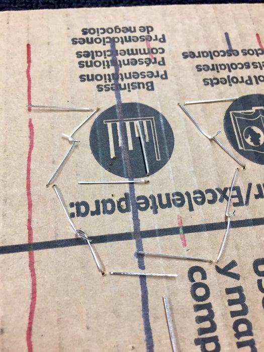
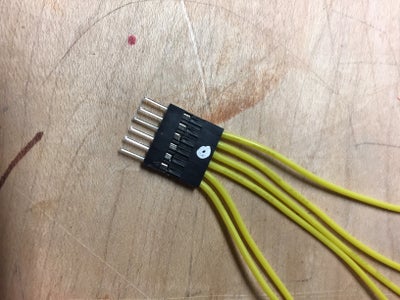
My scheme is to group them into rows; make a set of wires for the entire row and connect all of them to a single Dupont housing. One such “unit” is shown in the first photo. The end that connects to the IR sensor is a female connector; the other end is a group of male connectors (photo 2).
Line up the multiplexer board at one end of the table (photo 3). Plug in the wire group (photo 4) and then connect each end to consecutive IR sensors (photos 5 and 6). When you’re done with one row, it should look like photo 7.
Repeat for all the rows of sensors. Yes, I know, tedious. The finished board is shown in photos 8 and 9.
Step 22: Assemble and Install the RGB LED Rings
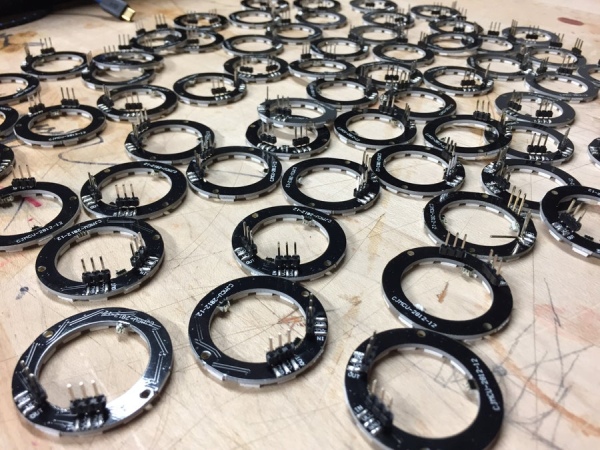
Repeating the process described earlier, solder two 3-pin sections of right-angle header to the pads on the bottom of each LED ring. When the solder is hard, carefully remove the black plastic from the header leaving only the pins. Yes, I know, tedious again! When you’re done, you should have a whole mess of these things — see photos.
Install the rings on the top surface by pushing each one through a set of six holes you previously made (photo 3). Be gentle because the pins can easily break off. When you’re done, the top surface should look like photo 4.
Congratulations, the top is done!
Step 23: Wire the LED Rings
Flip the cardboard over and you will see all the pairs of 3-pin groups from the LED rings poking through (see first photo). The six pins have the following functions: ground in, power in, data in, and ground out, power out, data out. This allows us to easily chain rings together using three-wire connectors (with female connectors on both ends). The result is a single, logical strip of RGB LEDS, which is easy to program as long as we carefully map out where each resides the logical array of LEDs. This information (along with the IR sensor indexes) is represented in one place in the code.
One problem with this strategy is that the resulting “strip” consists of 61 rings of 12 LEDs — a total of 732 LEDs! That’s a lot. The first problem is power: our three-wire connectors might be 24 or 26 AWG, which is not nearly big enough to carry current for all those LEDs. Second, the WS2812 LEDs that we’re using take time to pass the signal down the line, limiting our frame rate for animations.
The solution to problem one is to wire each column of rings directly to the main power line, that way a single chain consists of at most 72 LEDs. To solve the second problem, I break up the data signal into three groups — two groups of 22 rings, and one group of 17. Luckily, the FastLED library makes it easy to set this pattern up, while still begin able to treat the LEDs as a single strip in the code.
Start by adding all the three-wire connectors between pairs of adjacent rings (photos 2, 3, and 4). Pay close attention to the input and output patterns: make sure you are connection ground to ground, power to power, and data to data. On my rings, the data signal is always the inside two wires that face each other. The finished product is shown in photos 5 and 6. At this point we have columns of rings, but the columns are not connected to each other.
Next make power and ground bus wires using a heavy gauge, such as 20 AWG. I used the same strategy to power the IR rails: cut out a little piece of the insulation and solder the individual power and ground lines. See photos 7 and 8. Notice the connector: it has power and ground connected as you might expect, but there is also a long wire attached to the data pin. This wire carries data from the top of the previous column to the bottom of the next column. Attach it just as you would any of the three-wire connectors (photos 9 and 10), but then attach the blue wire to the data out pin at the top of the previous column (photos 11 and 12).
When all the power wires are connected, you will see a zig-zag pattern in the data lines that connects all the RGB LED rings into a single long logical strip (photo 13). In my design, I broke it into three logical strips, so you can see the three inputs (photo 14). Finally attach the power lines to the power supply (photo 15).
I also added a large, 1000uF coupling capacitor across the power lines to absorb big power fluctuations, especially at power-up.
Step 24: Wire and Connect the Microcontroller
I chose the Espressif ESP32 microcontroller for this project. It is a great chip: dual core, 160 or 240 MHz, with plenty of memory, lots of pins, and plenty of interesting special features. I worked with a few other people to develop ESP32 support for the FastLED library, in part to make this project possible. I’ll talk about the code in the next step.
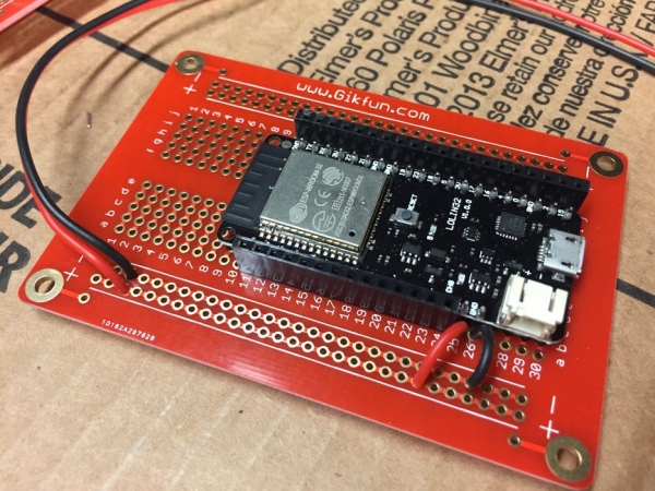
Wiring the microcontroller is fairly straightforward: we need four output pins for the IR selector; four input pins to read the IR sensors; and three output pins to drive the LED rings. I soldered my ESP32 onto a protoboard, then added female headers so that I can easily plug everything in as needed.
I also added power for the protoboard rails, which is also used to power the multiplexer boards. The full wiring set up is shown in photo 4.
Step 25: Add AC Power to the Power Supply
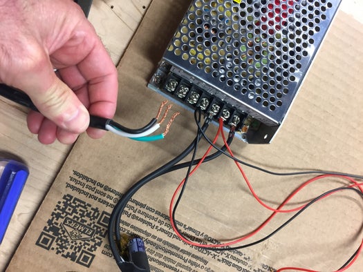
My power supply takes a three-wire AC input (110V). Carefully connect the three wires, including the green ground wire. ALSO: make sure the power supply is set for 110V — some of them have a switch, and my came set to 220V.
The bottom of the complete table surface is shown in the last picture.
Step 26: Configure and Install the Software
You can find my software at https://github.com/samguyer/ReactTable. It implements the four patterns you see in the demo video (solid, confetti, gears, and fire), but feel free to experiment with your own!
Unless you build and wire your table *exactly* the way I have, you might need to change some things in the configuration of the software:
Pins
I used the following pin assignments on my ESP32:
- IR channel selectors: pins 5, 18, 23, 19 — they happen to be next to each other on my board
- IR inputs: pins 32, 33, 34, 35 — also next to each other, and are input only.
- LEDs (broken into three sub-strips): pins 17, 16, 4
You will find all of these pin assignments (and descriptions) at the top of the sketch. If all you change are these pins, the modifications should be quick and easy.
LED and IR layout
If you change the number of cells or their layout/wiring on the table, you will need to change a few other things. First, fix the three #defines that specify the number of cells and the number of LEDs per cell (also in the configuration section at the top of the file).
Next, update the cell mapping. This information is stored in a global array of CellMapEntry structs called g_CellMap. You can ignore the x and y fields for now. The most important thing is to match up the IR index (which IR input the sensor is connector to) with the corresponding position of its ring in the LED strip ordering. On my table, the ordering is a little weird — the IR inputs are ordered in rows from left-to-right and top-to-bottom (the order of the array itself), while the LED rings are ordered in columns from bottom-to-top and right-to-left. Rather than try to figure out a fancy mapping function, I just explicitly write down all the indexes.
Compile and run!
Compile and upload to the ESP32! Note that I usually need to plug it in, otherwise it tries to draw all of the power it needs from the USB port of my computer!
Step 27: Creating Patterns
I have had a lot of fun creating the patterns that you see in the demo, but there are so many other things you could do. The code is not very complicated, and I’ve provided lots of useful utility functions to help you create new patterns.
Cell class
Almost all of the interesting stuff happens in the Cell class. There is one instance of this class for each cell (each pair of one IR sensor and one LED ring). Each pattern is implemented by a method in the class that reads the IR sensor and sets the colors of the LED ring — only for that cell. The main loop of the sketch just calls this method repeatedly at the given frame rate.
The solid pattern is a simple example:
void SolidPattern()
{
    if (m_new_pattern) {
            m_palette = RainbowColors_p;
            m_new_pattern = false;
    }
    uint8_t level = senseIRwithDecay(12, 4);
    setAllLEDsHue(level);
}
The first part initializes the pattern, if we have just switched from another pattern. Notice we can set the color palette differently for each pattern (and actually for each cell, if we want).
The next line reads the IR sensor, which produces a value between 0 and 255. You can think of this number conceptually as “distance” — smaller values are caused by something close to the table; larger values are something farther away (or nothing there).
This particular method incorporates a decay factor that causes the value to linger, leaving a trail. You can also read the immediate value using the method senseIR().
The last line sets all of the LEDs in the ring to the color hue given by the IR level. This value is an index into the current color palette. That’s it!
LEDs
There are two different sets of methods for setting LEDs in the ring. The first set directly sets each LED as a discrete element. You can specify the color either as an RGB (24 bit color) or as an index into the current palette (8-bit value). The index must be within 0 and LEDS_PER_CELL.
void setLED(int index, CRGB color);

void setLEDHue(int index, uint8_t hue, uint8_t brightness);

void setAllLEDs(CRGB color);

void setAllLEDsHue(uint8_t hue, uint8_t brightness);
The second set of methods treats the ring as a continuous space of pixels, so you can illuminate any logical position in the circle. For these methods, the index is a 16-bit fixed-precision number — the high 8 bits represent the whole number portion between 0 and 255, and the low 8 bits represent the fractional portion in units of 1/256. The methods below create the illusion of all of those positions by interpolating between the actual physical pixels. This is the method that the Gears mode uses to make the motion smooth.
void setPixel(uint16_t pos, CRGB color);

void setPixelHue(uint16_t pos, uint8_t hue, uint8_t brightness);
Source: NeoPixel Reactive Table
- What are the main components of the reactive table?
The table uses IR emitters, IR photodiode sensors, analog multiplexer boards, NeoPixel LED rings, and a microcontroller (ESP32). - How many cells and LEDs does the example table have?
The example has 61 cells, each with a 12-pixel LED ring, totaling 732 LEDs. - Can a single microcontroller read all 61 IR sensors directly?
No; the project uses four 16-channel analog multiplexers (CD74HC4067) to handle the 61 sensor inputs. - How are the IR emitters powered to match a 5V supply?
IR emitters are wired in series groups of three with a small current-limiting resistor (6.8–12 ohm) for 5V operation. - How do the IR photodiodes behave in the circuit?
Photodiodes are reverse biased with a 10K pull-up; the signal reads high with no IR and goes low when IR light is reflected. - What microcontroller and library are used for driving the LEDs?
An ESP32 is used, and the FastLED library drives the NeoPixels. - How is the NeoPixel data and power distributed to avoid voltage drop?
Columns of rings are powered directly with heavy gauge wire and the data line is split into three logical sub-strips to limit chain length and timing issues. - Where is the project code available?
The software is available at https://github.com/samguyer/ReactTable and includes provided patterns and configuration options. - What skills are needed to complete the project?
You need soldering, basic wiring, some Arduino/ESP32 programming, attention to detail, and patience. - How are LED rings attached to the board?
Right-angle 3-pin headers are soldered to the ring pads, pins pushed through pre-punched holes, and chains are formed with three-wire connectors.