Summary of Network Rivalry: a Low-Latency Game for the BBC Micro:bit
This tutorial guides users in building a low-latency multiplayer political simulation game on the BBC micro:bit using Microsoft MakeCode. It details a finite state machine for device states (Unassigned, Listen A/B, Team A/B), a simple integer-based signal protocol for network communication, and techniques to minimize display latency by editing JavaScript code. The project involves a user application and a master "root" controller to manage team conversions and network resets via radio transmission.
Parts used in the Network Rivalry Game:
- BBC micro:bit device
- Microsoft MakeCode editor
- 5 x 5 LED display
- Button A
- Button B
- Wireless radio module
- Master remote ("root") device
- JavaScript code blocks
In this tutorial, I will explain how to implement a basic multiplayer game on the BBC micro:bit with the following features:
- A simple interface
- Low-latency between button presses and screen updates
- A flexible number of participants
- Easy control over the game using a master remote (“root”) device
The game is essentially a simulation of politics. All players start out unassigned to any team, except for two players. One of these players is assigned to Team A, and the other is assigned to Team B.
The objective of the game for each player to be on the team with the majority of the players at the time that everyone is converted.
The diagram above illustrates a finite state machine, i.e. a specification of the states that the device can be in and the transitions between those states.
A state can be thought of as the current set of data that describes the memory of the device since it was turned on. Based on that data, the device may perform certain actions or react differently to user input.
A transition is a logical condition that, when true, causes the device to change its state. A transition can be from one state to any other state. A state may have multiple transitions.
The diagram above specifies the following states:
- Unassigned
- Listen for A
- Listen for B
- Team A
- Team B
A device running the game code may be in any one of these five states, but only one at a time, and only these five.
I will assume throughout the guide that you are using Microsoft’s MakeCode editor, which can be found at: https://makecode.microbit.org
The full implementation of the game can be found here:
https://makecode.microbit.org/_CvRMtheLbRR3 (“microbit-demo-user” is the project name)
And implementation of the master (“root”) network controller can be found here:
https://makecode.microbit.org/_1kKE6TRc9TgE (“microbit-demo-root” is the project name)
I will refer to these examples throughout my tutorial.
Step 1: Big Picture Design Considerations
Before we write any code, we need to think about what we want our end product to look like. in other words, what are the requirements of the application? What should our code tell the device to do when it is finished? I have divided the functionality of the main application into six categories, each of which can be considered from a different design perspective.
- We want to control the device’s actions based on its current state
- We want the device to react to user input
- We may want to display animations and graphics using the 5 x 5 LED display
- We want to initialize data values in the devices memory when the device boots up
- We want to transmit data wirelessly using the device’s radio
- We want to listen for and receive data over the device’s radio and process it accordingly
Allow me to go into a little bit more detail about each one.
1. We want to control the device’s actions based on its current state
Like most other programs, execution of the instructions specified by the code happens one line at a time. We want our device to execute certain instructions based on its internal state, as illustrated by the diagram at the top of this tutorial. We could write a series of conditionals after every block of code that checks the device should be doing, but this approach can get very messy very quickly, so we will instead be using an infinite loop that simply checks one variable, and based on that variable, executes a specific set of instructions or does nothing at all. This variable will be identified by the suffix “_state” in both our user application and our root application.
2. We want the device to react to user input
Despite normal execution of the code occurring sequentially, that is to say, one line at a time, we need our device to react to button presses while the main state loop is determining what the device should do at any given moment. For that purpose, the device has the capability of sending signals to the lower-level software that interacts with the hardware, triggering what’s called an event. We can write code that tells the device to do something when it detects a specific type of event.
3. We want to display animations and graphics using the 5 x 5 LED display
The mechanism to do this appears to be simple, but the block do display an image adds a hidden delay of 400 ms. Because we want our device to continue to execute its state loop with as little latency as possible, we will need to edit the javascript code to minimize the delay.
4. We want to initialize data values in the devices memory when the device boots up
Before our device does anything, the application needs to load its data into memory. This includes constant variables named for code readability, variables that contain images, which may be a part of an animation, and counter variables that need to start out at 0 to work properly. We will end up with a long list of variable names and their newly assigned values. As a personal style choice, I will denote constant values, i.e. values that I will never need to change, using ALL_CAPS. I will also prefix main variable identifiers with a category name that refers to a sort of object or type that the identifier falls under. This is in attempt to make the code easier to follow. I will never use a variable name like “item” or “x” because of the ambiguity that arises when trying to decipher the code.
5. We want to transmit data wirelessly using the device’s radio
This is actually a fairly simple task when using the MakeCode blocks language. We simply set all devices to the same radio group at boot time and then when we want to send a signal, we can pass a single number to the “Radio send number” block provided to us. It is important that the sender and receiver are working on the same radio group, because if not, they will be sending or receiving on different frequencies, and the communication will be unsuccessful.
6. We want to listen for and receive data over the device’s radio and process it accordingly
Taking in mind the same considerations as the previous item, we will listen for incoming transmissions the same way we will listen for user input: with an event handler. We will write a block of code that will examine any incoming signals and check if any action is to be taken without disturbing the main state loop.
In addition, we should briefly consider the design of the far simpler root application, a program that will allow a device to control the entire network. I will not spend much time on this as it is far simpler than the above design and much of it is simply repetition. I have divided the functionality of the root deice into three categories.
- We want to be able to select a signal
- We want to be able to transmit a signal
—
1. We want to be able to select a signal
This can be done by simply having a button iterates through the possible signals. Since there are only three, this approach will suffice. At the same time, we can have a loop that constantly redisplays the selected signal, allowing the user to press a button and see the selected signal appear on the LED display with very little latency.
2. We want to be able to transmit a signal
Since there are two buttons, we can designate one for selection and the other for confirmation. Like the user application, we simply send the signal over the network as a number. There is no other information required.
I will speak more about the simple signal protocol in the next section.
Step 2: The Signal Protocol: a Simple Language for Network Communication
The followings signals can be thought of as the set of all possible words that the devices can use to talk to each other. Because the network is so simple, there is not much to say, and so we can represent these three signals by simple integer values.
0. Reset
- Identifier in the code: SIG-R
- Integer value: 0
- Purpose: Tell all devices within range to drop what they are doing and act as if they were just booted up. If this signal reaches every device on the network, the entire network will be reset and the users can start a new game. This signal can only be broadcast by a root device.
1. Conversion A
- Identifier in the code: SIG-A
- Integer value: 1
- Purpose: Tell any device that is in state LISTEN_A, once they receive the conversion signal, to switch to state TEAM_A.
2. Conversion B
- Identifier in the code: SIG-B
- Integer value: 2
- Purpose: Tell any device that is in state LISTEN_B, once they receive the conversion signal, to switch to state TEAM_B.
Step 3: We Want to Control the Device’s Actions Based on Its Current State
At last, we can begin writing code.
First, Open up a new project in Make Code
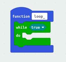
- Create a new function. I called mine loop because this is the core loop of the application
- Add a loop block that will repeat indefinitely. I used while(true) because a literal true will never be false, hence the control flow of the application will never exit the loop
- Add enough if-else blocks to check if the device is in any of its five possible states
- Create a variable to hold the current device state
- Create variables to represent each of the five possible states
- Note: It is OK that these variables do not have any assigned values yet. We will get to that. At this point, it is more important that we write clean, easy to read code
- Change each condition in the if-else blocks to be comparing the current state to one of the possible states
- At the bottom of the if-else blocks, add a pause for some number of milliseconds, and create a variable to hold that number. We will initialize it later. Make sure the variable has a descriptive name, such as tick or heartbeat. Because this is the core loop of the device, this pause will determine the speed at which the device executes the main loop, so it is a very important value, and is too important to be a magic number with no name.
Note: Don’t worry about the gray blocks in the third image. I’ll get to those later.
Step 4: We Want to React to User Input
Now, we want to tell the device how to handle button presses. One’s first thought might be to simply use the “When button is pressed” blocks in the input category, but we would like more granular control than that. We will use the “on event from (X) with value (Y)” block from the control category under the advanced section, because we are advanced in this tutorial.
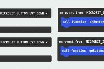
- Create four “on event from…” blocks.
- Two of these should should check the event source “MICROBIT_ID_BUTTON_A”
- Two of these should should check the event source “MICROBIT_ID_BUTTON_B”
- Of the two events targeting each button:
- One should check for the event of type “MICROBIT_BUTTON_EVT_UP”
- One should check for the event of type “MICROBIT_BUTTON_EVT_DOWN”
- Note: These options in all capital letters are labels that are used in the lower-level micro:bit code. They are simply placeholders that are later replaced by integers when the code is compiled to an executable binary. It is easier for humans to use these labels than to look up which integer to put in, though both would work the same way.
- I chose, as a matter of style, to have each “on event from…” block call a function that describes the raised event. While not strictly necessary, in my opinion this improves readability. If one wishes to do so, they can put they event-handling code inside the “on event from…” block itself.
- Note: The block of code that handles the device’s response to an event is intuitively called an “event handler”
- Add, in each event handler, the same if-else structure used to split control flow based on device state as the structure in the main state loop.
- Add assignment blocks that modify that state of the device as specified by our state diagram
- We know that when the device is in state UNASSIGNED, the device should react to button A pressed by a transition to state LISTEN_A, and to button B pressed by a transition to state LISTEN_B
- We also know that when the device is in state LISTEN_A or LISTEN_B, the device should react to button A released and button B released, respectively, by transitioning back to state UNASSIGNED.
- Finally, we know that when the device is in state TEAM_A or TEAM_B, the device should react to button A pressed and button B pressed by broadcasting SIG_A and by broadcasting SIG_B respectively.
- It is not necessary at this point to fill in the details of broadcasting signals. We will get to that later. What is important is that we instruct these functions to use the code that we will write by giving that block of actions a name, like broadcastSignalSIG_A, which describes what should be done at that point.
Step 5: We Want to Initialize Data Values in the Devices Memory When the Device Boots Up
At this point, we have used a lot variables (names for data), but we have not actually assigned values to those names. We want the device to load the values of all of these variables into memory when it boots, so we place the initialization for these variables in an “on start” block.
These are the values we must initialize:
- Signal constants, as per the signal protocol. The values MUST be:
- SIG_R = 0
- SIG_A = 1
- SIG_B = 2
- Note: I prefixed these constants with “EnumSignals” in order to denote that these variables are to behave as if they were part of an enumerated type called Signals. This is how these variables may be implemented in other programming languages. The definition and explanation of enumerated types is beyond the scope of my tutorial. One may Google it if they so desire. These prefixes are simply stylistic choices and are not at all essential for proper functioning of the program.
- State constants, which can be arbitrary as long as they have a value. I made a style choice to simply use integers ascending from 0, like so:
- UNASSIGNED = 0
- LISTEN_A = 1
- LISTEN_B = 2
- TEAM_A = 3
- TEAM_B = 4
- Note: I made the same style decision regarding prefixes for these variables as well. In addition, I will mention that everything about these assignments, the values and the order, is completely arbitrary. It does not even matter that these values are consistent from device to device, because they are only used internally and not for communication over the network. All that matters is that the variables have a value and that they can be compared to each other to see if they are equivalent or not.
- For readability, a constant called BOOT_STATE and set it to UNASSIGNED. This makes the fact that we reset to the boot state, instead of a more arbitrary state, more explicit when the device receives a reset signal, which we will implement later on.
- Animation constants, used in the following step to create animations that allow for extremely low-latency interruption via user input. We have not used these thus far, but they will certainly be explained and used in the following section. The meaning of some of these should be intuitive due to their names.
- TICKS_PER_FRAME_LOADING_ANIMATION = 50
- MS_PER_DEVICE_TICK = 10
- MS_PER_FRAME_BROADCAST_ANIMATION = 500
- MICROSECONDS_PER_MILLISECOND = 1000
- NUMBER_OF_FRAMES_IN_LOADING_ANIMATION = 4
- Another variable for animation, this time a counter that is definitely not constant. Like most counters, we initialize it to 0
- iTickLoadingAnimation = 0
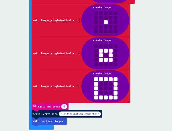
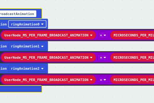
- Create two series of variables to hold frames of animations. The first, which I call the “loading animation”, should have four images (which you may have guessed by the last constant initialization), and the second, which I call the “broadcast animation”, which should have three images. I recommend naming the variables to correspond to frames of the animation, e.g. ringAnimation0, ringAnimation1…
- Create the same image values as I did or create more original and cooler images.
- Last but not least, we must set the radio group of the device to 0 using the “radio set group (X)” block
- Optionally, write the message “Initialization complete” to serial output to tell the user that everything went swimmingly.
- Now that we are done setting up the device, we can call our state loop function.
Step 6: We Want to Display Animations and Graphics Using the 5 X 5 LED Display
And now for something completely different.
We want to display a few animations and a few characters, but we don’t want to interrupt the main state loop. Unfortunately, the blocks that display images and text strings have a delay of 400 ms by default. There is no way to change this without editing the javascript representation of the code. So, this is what we will do.
- Create a function for each image. This will allow one to use a single block to display the image instead of editing javascript every time. In this specific program, no image is used more than once, but I still think this style makes the code easier to read.
- Add, in each new function, a “show image (X) at offset 0” block with the corresponding image variable name replacing (X)
- Add, in the main state loop. “Show string (X)” blocks to each block besides the one that handles state UNASSIGNED. Add a character for the device to display to indicate its different states. Here is what I did:
- LISTEN_A: ‘a’
- LISTEN_B: ‘b’
- TEAM_A: ‘A’
- TEAM_B: ‘B’
- For state UNASSIGNED, place a call to a function that will update the loading animation. We will fill in the details of this function below.
- Switch to javascript mode.
- Find every call to X.showImage(0) and basic.showString(X)
- Change every single one to either X.showImage(0,0) or basic.showString(X,0)
- Adding this extra argument will set the delay after the action to 0. By default, this is left out, and the device will pause for 400 ms after the execution of each of these blocks.
- Now, we have a near latency-free mechanism to display our images in our animation blocks, which we can now build
First, we will build the relatively simple broadcast animation function. It is simpler because we don’t want the user to be able to do anything until the function is complete, so as to stop them from spamming the broadcast function. To accomplish this, we can simply keep control flow restricted to the block until the function is complete, which is standard behavior.
- Create a function that will display broadcast animation.
- Inside that block, add three function calls, one to each frame of the animation, in the order that they should be displayed
- Add a “wait (us) (X)” block after each call to an image-displaying function.
- Note: This block, from the advanced control section, will go even further than “pause (ms) ” in that it will completely freeze the processor until the specified time has elapsed. When the pause block is used, it is possible that the device will perform other tasks behind the scenes. This is impossible with the wait block.
- Replace (X) with (MS_PER_FRAME_BROADCAST_ANIMATION x MICROSECONDS_PER_MILLISECOND)
- The animation should now function properly
Second, we will build the mechanism for displaying the loading animation. The idea behind this is to update the LED display at a specific interval, which we define in the variable MS_PER_DEVICE_TICK. This value, the device tick length, is the number of milliseconds that the device pauses after completing each iteration of the state loop. Because this value is small enough, we can update the display once during each iteration of the display loop and it will appear to the user that the animation is progressing seamlessly, and when the state changes, there will be very little latency between the user’s input the display being updated. By counting ticks, which we do with the iTickLoadingAnimation variable, we can display the appropriate frame of the animation.
- Create a function that will update the loading animation
- Add a condition to check if the the tick counter has reached its maximum value. This condition will be true if the tick counter’s value is greater than the number of frames in the loading animation multiplied by the number of ticks to display each frame
- If the condition is true, reset iTickLoadingAnimation to 0
- Add a block of if-else conditions. These will determine which frame of the animation to display.
- For each frame of the animation, if the tick counter is less than the number of ticks in each animation multiplied by the frame number of the animation (starting at 1), then display that frame, else check if the next frame is the one to be displayed
- At the bottom of the block, increment iTickLoadingAnimation
- The animation should now function properly
Note: All of the gray blocks that appear in my example are generated when one edits the javascript representation of a block. It simply means that the block represents javascript code that cannot be represented using the standard set of blocks and must be edited in text form.
Step 7: We Want to Transmit Data Wirelessly Using the Device’s Radio
This step is far shorter than the previous. In fact, it’s probably the shortest step in this whole tutorial.
Recall that when we programmed the device’s response to user input, I had two blocks in the screenshot that were not explained in that section. These were calls to functions that send signals over the radio. More specifically:
- On button A pressed:
- If the device is in state TEAM_A:
- Broadcast signal SIG_A
- If the device is in state TEAM_A:
- On button B pressed:
- If the device is in state TEAM_B
- Broadcast signal SIG_B
- If the device is in state TEAM_B
Create this functions if they do not exist already.
In each function:
- Call the broadcast animation function. This will block anything else from happening until it completes, which will be in MS_PER_FRAME_BROADCAST_ANIMATION * 3 = 1.5 seconds. The constant is multiplied by three because there are three frames in the animation. This is arbitrary and more can be added if the aesthetic upgrade is great enough. A second purpose of this animation is to prevent a user from spamming the broadcast function.
- Add a “radio send number (X)” block, where is the signal constant mentioned in the function name
That’s all one needs to broadcast over the radio.
Step 8: We Want to Listen for and Receive Data Over the Device’s Radio and Process It Accordingly
This is the final step to create the main application.
We are going to tell the device how to process incoming radio signals. First, our device is going to name the received signal. Then, based on the value of that signal, it will decide what action to take, if any.
First:
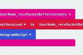
- Create a block of code starting with an “on radio received (X)” block.
- Optionally, assign that received value to another variable with a more descriptive name.
- Call a function that will process the signal
Second, in the signal processing function:
- Create a block of if-else statements that branch control flow based on the value of the signal.
- If the signal was SIG_R
- Set the device’s state to BOOT_STATE (this is why we created this constant earlier)
- If the signal was SIG_A and if the current state is LISTEN_A
- Set the device’s state to TEAM_A
- If the signal was SIG_B and if the current state is LISTEN_B
- Set the device’s state to TEAM_B
That’s it. The application is finished.
Source: Network Rivalry: a Low-Latency Game for the BBC Micro:bit
- What is the objective of the game?
The objective is for each player to be on the team with the majority of players when everyone is converted. - How does the device react to user input during the main loop?
The device uses event handlers triggered by button presses to change its internal state without stopping the main execution loop. - Why must the showImage and showString functions be edited in JavaScript?
Editing these blocks allows the user to set the delay argument to zero, removing the default 400 ms pause to ensure low latency. - What are the three signals defined in the protocol?
The signals are Reset (SIG-R), Conversion A (SIG-A), and Conversion B (SIG-B). - Can any device broadcast the Reset signal?
No, the Reset signal can only be broadcast by the root device. - How does a device transition from LISTEN_A to TEAM_A?
The device transitions when it receives the SIG-A signal while currently in the LISTEN_A state. - What happens when a device receives the SIG_R signal?
The device's state is set to BOOT_STATE, effectively resetting the network as if just booted up. - How is the radio group configured for the devices?
All devices are set to the same radio group at boot time to ensure successful wireless communication. - What is the purpose of the tick variable in the main loop?
The tick variable determines the speed at which the device executes the main state loop by setting the pause duration between iterations. - How does the loading animation update without blocking the main loop?
The animation updates by checking a tick counter within the main loop and displaying specific frames based on the elapsed ticks.