Summary of Power factor measurement using Atmel AVR Micro-Controllers
This article explains power factor measurement principles, distinguishing between resistive, inductive, and capacitive loads where current lags or leads voltage. It details a project using Zero Cross Detection via an LM358 comparator to measure the phase angle. The system steps down high voltage and current using Potential Transformers (PT) and Current Transformers (CT) to safe levels for the microcontroller and IC. Results are displayed on a 16x2 LCD controlled by an ATmega 8 or ATmega16 microcontroller.
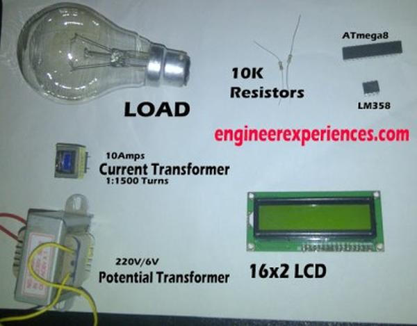
Parts used in the Power Factor Measurement Project:
- LM358 IC
- 16x2 LCD
- ATmega 8 Microcontroller
- ATmega16 Microcontroller
- Potential Transformer (PT)
- Current Transformer (CT)
- Sine Generator
To learn about the power factor measurement, you should have a basic knowledge of power factor. There are three types of loads.
- Resistive
- Inductive
- Capacitive
When we apply AC voltage to resistive loads it will not change the current wave form. But inductive loads will force to lag the current waveform and in the case of capacitive loading it will force to lead the current waveform than voltage waveform.
You can see the waveforms of inductive load. The phase shift of 30 degree is present in the current waveform.
The power factor is basically the “angle cosine of that lagging current”. In simple words, current is lagging by voltage with some angle and if we take the cosine of that angle we will get power factor.
Zero Cross Detection:
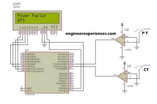
Zero cross detection is a method which can enable us to measure the time between voltage and current. In this technique we get a high value (i.e. 1) whenever a zero will cross the system. There are many ways to implement it. But remember, this technique is the heart of this project so implementation must be accurate. In this project we implemented zero crossing using LM358 an 8 pin IC having dual amplifiers in it. In zero crossing, we have to get a “high” value during crossing of zero in waveforms. So to get that value we use amplifier as a comparator which will compare the non inverting reference value and then act accordingly.
We will use a 16×2 LCD to show our results and ATmega 8 or ATmega16 can be used for the project. In the simulation, take upper sine generator as output of Potential Transformer (PT) and lower sine generator as output of Current Transformer (CT). The reason behind using CT and PT is, we cannot give high voltage to the IC LM358. It will burn the IC badly. So first step down the voltage and step down the current at such extent that the highest peak of current and voltage is not more than 5V. If you have no idea of using CT and PT in the real systems then see the links below.
Read More: Power factor measurement using Atmel AVR Micro-Controllers
- What is the formula for calculating power factor?
Power factor is the cosine of the angle by which the current lags behind the voltage. - How does an inductive load affect the current waveform?
An inductive load forces the current waveform to lag behind the voltage waveform. - Can high voltage be applied directly to the LM358 IC?
No, high voltage must be stepped down because applying it directly will burn the IC badly. - What components are used to step down voltage and current?
A Potential Transformer (PT) and a Current Transformer (CT) are used to step down the values. - What is the maximum peak value allowed for current and voltage in this project?
The highest peak of current and voltage should not exceed 5V. - Which microcontrollers are suitable for this project?
ATmega 8 or ATmega16 can be used for the project. - How is zero cross detection implemented in this design?
It is implemented using the LM358 as a comparator to detect when waveforms cross zero. - What type of display is used to show the results?
A 16x2 LCD is used to show the measurement results.