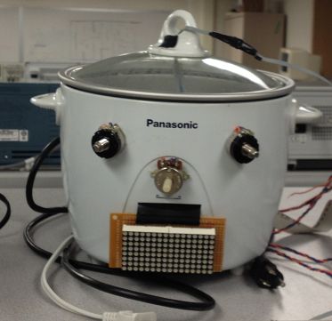
Precise time and temperature control are critical when cooking. Slight deviations in either temperature or cooking time can ruin delicate ingredients. Despite this fact, most modern day stovetops provide no data regarding their current temperatures and do not have built in timers. The stovetops that do provide these functionalities are often expensive and require specialized cookware. As our final project for ECE 4760 at Cornell University, we decided to build a programmable temperature and time controlled cooker that would use traditional thermal conduction to cook food regardless of the cooking vessel’s material. The cooker can be used for a variety of purposes ranging from simply boiling the perfect 6-minute soft-boiled egg to sous-vide cooking a piece of delicate white fish. Quickset options can be programmed into the cooker allowing for easy preset operation.
High Level Design
Overview
Our aim for this project was to make temperature controlled cooking accessible to those without culinary training and/or professional kitchen appliances. Our project focuses on immersion cooking methods such as poaching, simmering, boiling, or sous vide cooking. We decided to focus on these cooking methods as they require very little technique but rather precise temperature control and cooking time. Recipes often call for specific temperatures and timings, but as most modern-day stovetops provide no temperature or timing feedback, it is difficult to know when these requirements have been met. By being able to set precise timings and temperatures, users simply have to place the food in the cooker when prompted and let the cooker handle the rest in order to create a perfectly cooked dish.
Rationale and Motivation Behind our Project
Cooking foods at controlled temperatures is a very difficult thing to achieve for extended periods of time. Using traditional gas stovetops, it is almost impossible to maintain a specific temperature for a set amount of time. However, by controlling the heat source electronically using a feedback loop, we can continuously measure the temperature and adjust it as necessary. Our project is designed to maintain any temperature between 45 and 100 degrees Celsius for extended periods of time with minimal deviation in temperature.
Background Math
For background math, we will be discussing our PID controller and our voltage-temperature sensor calibration and equation derivation. For our temperature control feedback loop, we utilized a proportional-integral-derivative (PID) controller. The PID controller measures the deviation between the desired result and the current measurement and outputs a value that is calibrated to reach the desired value with minimal overshoot or undershoot. Our PID controller is sourced from the AVR221 application. The PID controller is composed of three terms: the proportional term, integral term, and derivative term. These three terms are summed together to calculate the output of the PID controller. The PID equation is defined as:
where:
- Kp : Proportional term
- Ki : Integral term
- Kd : Derivative term
- e : Error term
- t : Time of measurement
- τ : Integration variable ( 0 -> t)
For our final PID values, we selected P = .07, I = .04, and D = .05. All of these values are low as our system changes very slowly and adjustments to the system take a long time to take effect due to the high specific heat of our immersion liquid (water). For our voltage-temperature sensor calibration, we utilized the LM35 temperature sensor to measure the temperature of the immersion liquid. The LM35’s datasheet provided us with the below voltage-temperature curve.
After some experimentation, we discovered that the given curve did not fit our measured results. To properly calibrate our temperature readings we swept across numerous temperatures and measured the voltage output of the LM35 using the microcontroller’s built in ADC. We then plotted these values and performed linear regression to find a line of best fit that we used as our voltage-temperature equation
Logical Structure
Our project is composed of three discrete modes of operation: input, heating, and cooking. These stages are further split into smaller states for implementation purposes. These smaller states can be seen in the software finite state machine shown in Figure 10.
During input mode, the heating element remains off and the system waits for user input. During this mode, the temperature desired and the cooking time should be set using either the three analog knobs or the UART computer interface. Once the temperature and cooking time are set, the system waits for the mode switch to be moved from off to on. Once the switch is moved to the on state, the system stores the desired temperature and cooking time and transitions into heating mode.
During heating mode, the cooker’s heating element heats up the cooking vessel to the desired temperature. During heating mode it is possible to switch between the LED display showing current temperature and desired temperature by toggling the display mode switch. The microcontroller controls the cooker by reading the temperature probe submerged in the cooking liquid and switching the relay inside the power box. When the relay is switched on, the cooker’s heating element is connected to the main power line and current flows through the heating element. This current flow causes the heating element to heat up. Through thermal conduction, both the cooking vessel and the cooking liquid begin to heat up as well. Once the desired temperature has been reached in the cooking liquid, the relay is turned off and a buzzer sounds. This buzzer signals the user that food should be placed into the cooker as the desired temperature has been reached. The cooker then transitions into cooking mode.
In cooking mode, the cooker begins to count down the desired cooking time recorded during input mode. During this mode, the cooking vessel will maintain the desired temperature by turning on and off the relay according to the readings from the immersed temperature probe. The cooker counts down until the timer reaches 0 and then a buzzer goes off to signal the user that the food has finished cooking. The buzzer continues to sound until the mode switch is set to input mode. At this point the cooker moves back into input mode to wait for further instructions. If the desired cooking time is left at 0, the system will beep immediately.
Hardware and Software Tradeoffs
In our hardware design, we decided to increase the hardware complexity by adding analog potentiometers for setting the temperature and time and building our own LED display screen. While we could have used an LCD display to display temperature and cooking time information, we decided to build our own LED display as it allowed us to print to a larger font. Despite the LED display being very difficult to build and program, it provides a larger and brighter display compared to the LCD display. We decided to implement analog potentiometers for setting the temperature and cooking time so that the system could be used independently of the UART computer interface. While our cooker can be programmed using the serial UART connection to a PC, it can also operate independently using only the analog potentiometers.
In our software design, we decided to use the Tiny Real Time (TRT) kernel written by Dan Henriksson and Anton Cervin as it allowed us to easily schedule tasks at set intervals and synchronize variables across multiple tasks. While using the TRT kernel decreased the amount of flexibility we had in writing our software, it ultimately made scheduling software tasks a lot easier.
Relevant existing patents, copyrights, and trademarks
There are no existing patents, copyrights or trademarks that our project infringes on. While numerous patents exist regarding temperature controlled cookers (e.g Patent EP2661944 A2 & Patent WO2012092683 A3), they utilize inductive heating surfaces which we do not use. The patent closest to our design that we found was Patent CA2722383 A1 which describes a temperature controlled heating element. However, this patent still does not apply to our project as it describes controlling the heating element’s temperature using electrical sensors within the heating coil while our system measures the temperature of the food’s immersion liquid. We utilize the Tiny Real Time (TRT) kernel and its supplemental UART libraries, both of which are filed under the “Beer-Ware License” by Joerg Wunsch. We also utilize the generic PID Controller code created by Atmel for the AVR221 application.
Hardware
Our overall hardware design is composed of numerous subsystems. The various subsystems can be seen in the figure below
The following subsystems compose our overall system:
- Atmel Atmega 1284P Microcontroller
- Analog Inputs
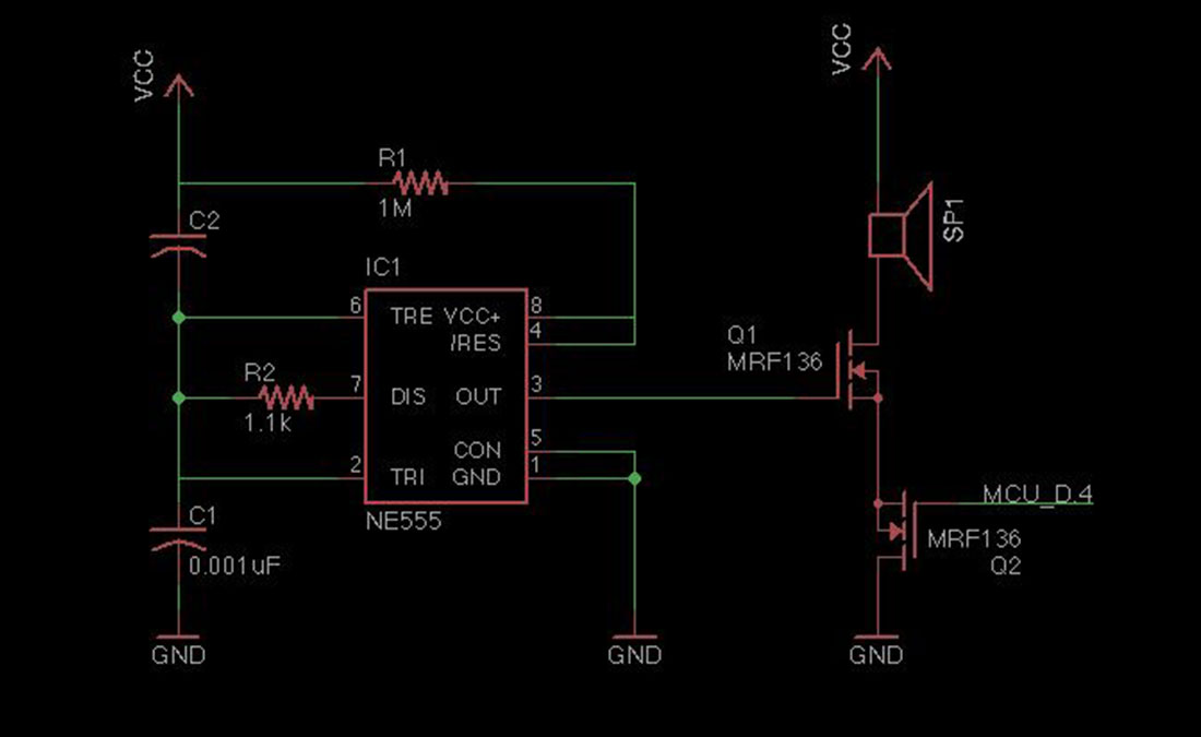
- Buzzer Sound Subsystem
- LED Display
- Temperature Sensor
- Power Supply and Heating Element
Microcontroller
Our microcontroller, an Atmel Atmega 1284P, is the logic controller of our system. Our microcontroller is mounted on a custom PCB produced by Professor Bruce Land of Cornell University. In addition to the microcontroller, the PCB includes an external oscillator, voltage regulators, and a FTDI serial module. The majority of the microcontroller’s functionality will be covered under the software design section. The microcontroller performs the following functions:
- Controls the power supply relay to turn on and off the heating element.
- Reads the temperature probe and calculates the current temperature.
- Reads the analog inputs to correctly set the desired temperature and cooking time.
- Turns on and off the piezoelectric buzzer.
- Sends messages to display on the LED display.
Parts List:
| Part | Source | Unit Price | Quantity | Total Price |
|---|---|---|---|---|
| Perf Board | Allelectronics | $1.50 | 2 | $3.00 |
| 500 Ohm Pot | Allelectronics | $0.50 | 2 | $1.00 |
| 10k ohm pot | Allelectronics | $2.00 | 2 | $4.00 |
| 74HC164N Shift Register | Digikey | $0.43 | 5 | $2.15 |
| LED Display | eBay | $1.80 | 2 | $3.60 |
| Rice Cooker | Fry’s Electronics | $34.99 | 1 | $34.99 |
| Temperature sensor | Digikey | $1.57 | 1 | $1.57 |
| Gang Box | Lowes | $0.94 | 1 | $0.94 |
| Combination Wall Plate | Lowes | $0.88 | 1 | $0.88 |
| Electrical Outlet | Lowes | $0.59 | 1 | $0.59 |
| Electrical Switch | Lowes | $0.69 | 1 | $0.69 |
| Sainsmart Relay module | Amazon | $10.00 | 1 | $10.00 |
| Microcontroller Atmage 1284P | ECE 4760 Lab | $5.00 | 1 | $5.00 |
| Piezoelectric Buzzer | Chinasound | $1.62 | 1 | $1.62 |
| Protoboard | ECE 4760 Lab | $6.00 | 1 | $6.00 |
| Microcontroller PC Board | ECE 4760 Lab | $7.00 | 1 | $7.00 |
| Serial Connector | ECE 4760 Lab | $1.00 | 1 | $1.00 |
| Header Pins | ECE 4760 Lab | $0.05 | 56 | $2.80 |
| DIP Switches | ECE 4760 Lab | $0.31 | 2 | $0.62 |
| 555 Timer | ECE 4760 Lab | $0.10 | 1 | $0.10 |
| n-channel MOSFETs | ECE 4760 Lab | $0.02 | 2 | $0.04 |
| Plastic tubing | Scrap lying in Lab | $0.00 | 6 in | $0.00 |
| Wiring | ECE 4760 Lab | $0.00 | 10 ft | $0.00 |
| Total | $87.59 |
For more detail: Precision Cooker: A Temperature Controlled Cooker Using Atmega1284