Summary of PROGRAMMABLE TIMER CIRCUIT ATTINY25
This article details an ATtiny25-based programmable timer circuit designed to control devices like electromagnetic bolts. It outlines seven operational modes, including simple timing, interrupt handling, restart functions, and sequence programming. The device allows users to define specific on/off sequences for automated gate or lock control, triggered by a push button.
Parts used in the Programmable Timer Circuit:
- ATtiny25 microcontroller
- Push button
- Electromagnetic bolt (solenoid)
- Jumper settings
- Schematic diagram components
- Assembly components
ATtiny25 Programmable Timer To describe the operation of the device, we will use an example – control of the electromagnetic bolt mounted in the wicket. In the simplest version we require that the push… Electronics Projects, Programmable Timer Circuit ATtiny25 “avr project, microcontroller projects, “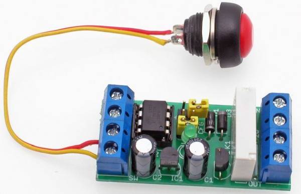
ATtiny25 Programmable Timer To describe the operation of the device, we will use an example – control of the electromagnetic bolt mounted in the wicket. In the simplest version we require that the push button attaches the bolt electromagnet for a certain length of time, sufficient to reach the gate. Then, the solenoid should be turned off. When analyzing the situation more precisely, we find that the solenoid does not have to be turned on when it reaches the gate, and only when it reaches the gate. So we teach the device the following sequence: output disabled for 10 seconds, then turned on for 3 seconds, then temporarily off and end learning. From now on, after pressing the button, the device will perform exactly the same sequence that will trigger the lock after 10 seconds, once we reach the gate, stay drawn for 3 seconds and finally be released. ATtiny25
Diagrams showing action each mode and corresponding to it jumper setting
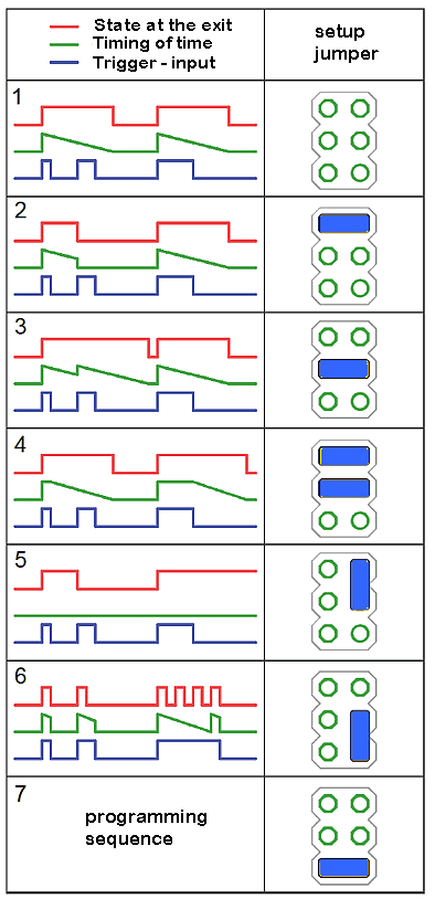
Programmable Timer Mode 1: Simple timer. As soon as the button is pressed, it starts playing the sequence until it is finished. During playback does not respond to the button.
Programmable Timer Mode 2: Interrupt timer. As in the first mode, but pressing the button during playback will immediately end the playback. As a result, the sequence can be aborted at any time by pressing the button again.
Programmable Timer Mode 3: Timer with restart. As in the first mode, but pressing the button during playback starts playing again.
Programmable Timer mode 4: End time switch. At the moment of pressing the button, it sets the first state of the sequence at the output and remains as long as the button is pressed. When the button is released, it starts playing the sequence, at that time it does not respond to the button.
Programmable Timer mode 5: Bistable switch. Each subsequent pressing of the button changes the state of the output to the opposite. The programmed sequence is not executed.
Programmable Timer 6: loop play. At the time when the button is pressed, a programmed loop sequence is output. Releasing the button immediately completes the sequence playback.
Programmable Timer 7: Sequence programming.
PROGRAMMABLE TIMER CIRCUIT SCHEMATIC ATTINY25
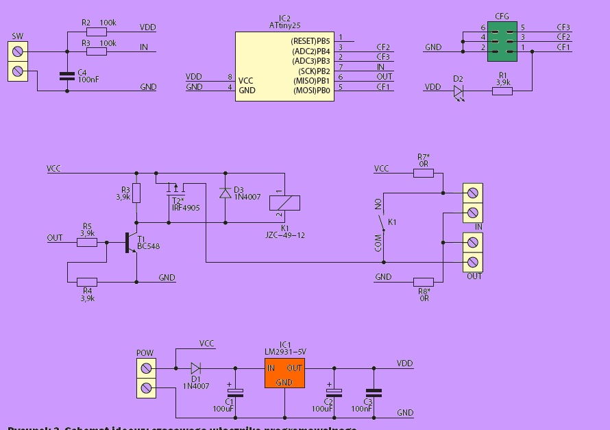
The schematic diagram Programmable Timer of the device is shown in Figure 2, and the assembly in Figure 3. The microcontroller application is straightforward and requires no discussion, just like assembly. All “power” of the programmable switch is included
Source: PROGRAMMABLE TIMER CIRCUIT ATTINY25
- What is the primary function of this project?
The device controls an electromagnetic bolt by playing a programmed sequence of output states after a button press. - How many operational modes does the timer support?
The timer supports seven distinct modes ranging from simple timers to sequence programming. - Can the playback be stopped early in Mode 2?
Yes, pressing the button during playback in Interrupt timer mode immediately ends the sequence. - What happens if the button is pressed during Mode 3 playback?
In Timer with restart mode, pressing the button causes the sequence to start playing again. - Does Mode 5 execute the programmed sequence?
No, Bistable switch mode changes the output state to the opposite without executing the programmed sequence. - How does Mode 6 handle the sequence loop?
Releasing the button in loop play mode immediately completes the sequence playback. - What component is used to trigger the device operation?
A push button is used to attach the bolt electromagnet and trigger the timer sequences. - Is assembly required for the microcontroller application?
Yes, the text states that the microcontroller application requires assembly.