
Summary of Programming adapter from 10 pin to 6 pin for AVRs
This article describes creating a compact programming adapter for AVRs by converting a standard 10-pin jack to a 6-pin jack. The project addresses space constraints in time-lapse modules by reducing connector size while maintaining functionality through specific wire mapping and assembly techniques.
Parts used in AVR Programming Adapter:
- 6 pin jack
- 10 pin jack
- 10 wire flat cable (trimmed to 6 wires)
- Sticky tape
- Pliers
- Stress relief brackets
This is the last one of my ‘Things that make life easier’ series, I published in the last few days.
It’s very simple, but most of the time the simple things are the most helpful.
I always used the big 10 pin jack for programming my AVRs because my programmer also had the 10pin jack.
With the time lapse module for the rollei camera a new requirement came up: Space. I wanted to make it as small as possible, so I changed from 10pin to a 6 pin jack.
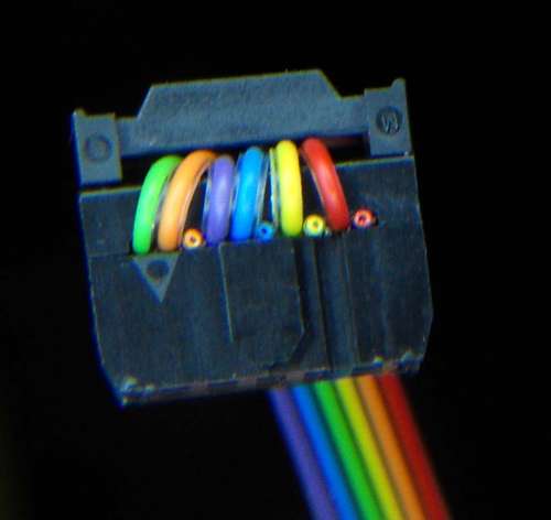
This is how to make a working connection between a 10pin and a 6pin jack.
You need one of each jack (6pin and 10pin) and a 6-wire flat cable.
Step 1 Pin assignment
Take a look at the pin assignments of the first pictures and the colors of the flat cable in the second picture.
That gives us:
RED MISO
Orange VCC
yellow SCK
green MOSI
blue Reset
violet GND
Step 2 Prepare the flat cable
It is difficult, if possible at all, to buy a 6 wire flat cable. So first of all take a 10wire flat cable and trim off four wires. I chose to rib off brown and the grey, white and black ones.
Then make a clean cut between the individual wires for about 4cm on one end of the cable. Make sure not to cut into the isolation of the wires!
Step 3 Reorder the wires
So first remind yourself on step 2 and which color is assigned to which function, we get for the 10pin jack the sequence:
1 Mosi green
2 VCC Orange
3 not connected, free
4 GND violet
5 Reset blue
6 GND violet
7 SCK yellow
8 GND violet
9 Miso red
10 GND violet
As we only have one violet wire, we can choose which pin we would like to take. They are interconnected in the 10pin jack of the programmer anyway.
Step 4 Fix the wires
It is very difficult to arrange all 6 wires to the right position in the 10 wire jack before closing it. So we do a little trick.
Take some sticky tape and place it face up on the table. Now we start sorting the wires one by one and stick it on the tape. When there is a gap, we insert a spare wire.
If you have all wires in the right order close the sticky tape and keep them in place. Once you finished this, get the aligned wires into the 10-pin jack and slowly close the housing.
Step 5 Close the brackets
If all wires seem to be o.k. close the two parts with a pair of pliers. Be careful not to damage the jack to much. There are also special tools for this. After the jack is closed, cut off the excess part with the sticky tape and add the stress relief brackets.
Step 6 Use it
Before you connect the programmer and an PCB you should measure if all contacts are established in the right order.
Once you have done this: GO and use it.
If you did it wrong, like my first version: Do it again… 😉
For more Detail: Programming adapter from 10 pin to 6 pin for AVRs
-
Why change from a 10 pin to a 6 pin jack?
The change was made to save space for the time lapse module on a rollei camera. -
How do you get a 6 wire flat cable if they are hard to buy?
You take a 10 wire flat cable and trim off four wires, specifically removing brown, grey, white, and black ones. -
What is the color assignment for the MISO function?
The red wire is assigned to the MISO function. -
How can you arrange wires in the correct order before closing the 10 pin jack?
You use sticky tape placed face up on a table to sort and hold the wires in the right sequence before inserting them. -
Which pins on the 10 pin jack are connected to GND?
Pins 4, 6, and 8 are connected to GND using violet wires. -
What tool is recommended to close the brackets of the jacks?
A pair of pliers should be used to close the two parts, though special tools are also available. -
What must be done before connecting the programmer to a PCB?
You must measure to ensure all contacts are established in the right order.
