Summary of Rotary Encoder Interfacing with ATmega8 Microcontroller
This tutorial details interfacing a rotary encoder with an ATmega8 microcontroller to detect shaft position and rotation direction. The system uses the encoder's output pulses to increment or decrement a binary count displayed on eight LEDs. Capacitors are employed to mitigate contact bouncing, ensuring accurate readings. The code monitors falling edges on specific pins to determine clockwise or anti-clockwise movement, operating at a default 1MHz internal clock without fuse bit configuration.
Parts used in Rotary Encoder Interfacing with ATmega8 Microcontroller:
- ATMEGA8 microcontroller
- Connecting pins
- AVR-ISP PROGRAMMER
- 220Ω resistor
- LED (eight pieces)
- 1KΩ resistor
- 220Ω resistor (2 pieces)
- 100nF capacitor (2 pieces)
- Bread board
- Rotary encoder module
In this tutorial we are going to interface a rotary encoder with ATmega8 microcontroller. ATmega8 is atmel’s microcontroller series designed for embedded applications. Rotary encoder is used to know the position of movement and angular movement of a motor or axis. It’s a three terminal device usually, with power and ground pin counts to five. A rotary encoder module is shown below.
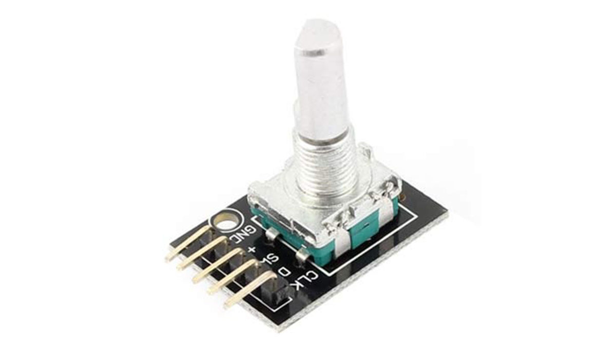
The pins of a rotary encoder are:
- Ground.
- Positive connected to +5V
- Output signal A pin
- Output signal B pin
- Clock pin or common pin.
The ENCODER provides pulses representing the change in the shaft position for the systems to understand. Consider a ROTATORY ENCODER is powered up and the shaft is moved.
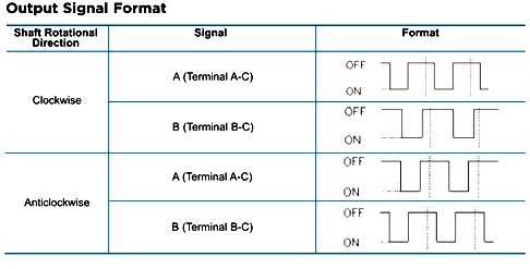
As shown in above table, consider the shaft is moved clock wise. With this there will be Falling Edge at the A terminal then at B terminal.
Consider the shaft is moved Anti clock wise. With this there will be Falling Edge at the B terminal then at A terminal.
This edge will occur once for 360/20 = 18 degrees (This is for a Encoder with 20 position, this changes from type to type, higher the count greater the accuracy).
With both above conditions, we can get direction and degree of rotation. Thus we get required parameters for getting the position of a shaft.
Components
Hardware: ATMEGA8, connecting pins, AVR-ISP PROGRAMMER, 220Ω resistor, LED (eight pieces), 1KΩ resistor, 220Ω resistor (2pieces), 100nF capacitor (2 pieces ), bread board.
Software: Atmel studio 6.1, progisp or flash magic.
Circuit Diagram and Working Explanation
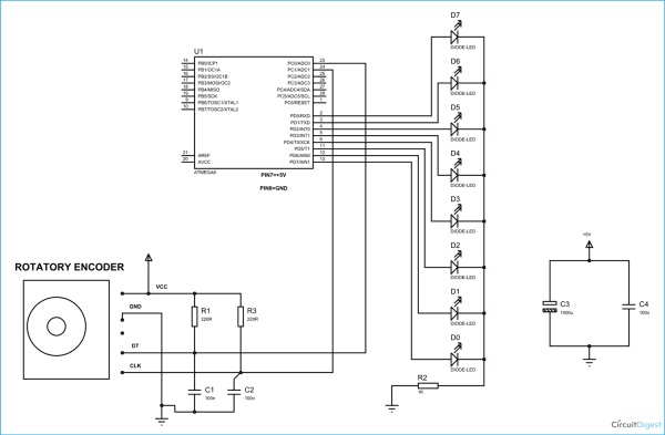
The capacitors here are for neutralizing the contact bouncing effect in ENCODER. Without those capacitors there will be some serious problems in position reading.
When the shaft is moved there will be time difference between two output pins output. The ATMEGA8 will recognize this time difference for clockwise of Anti clock wise rotation.
If the rotation is clockwise the binary count is incremented by one, and this count is shown in LED port as shown in figure.
If the rotation is Anti clock wise the binary count is decremented by one and the binary count is shown at LED byte.
Remember here we are not setting any fuse bits of atmega8, So the controller will be working on 1Mhz default internal crystal.
Working of interfacing rotary encoder with ATmega8 microcontroller is explained in below code.
Code
include
// header to enable data flow control over pins
define F_CPU 1000000UL
//telling controller crystal frequency attached
include
//header to enable delay function in program
int main(void)
{
        DDRD = 0xFF;// portD as output

         PORTD =0;

         DDRC= 0;//portC as input

         int count =0;

         int i=0;

while(1)

{

         if (i==0)

                  {

if ((bit_is_clear(PINC,0))||(bit_is_clear(PINC,1)))

//If any Encoder pins show falling edge execute lop

         {

             i= 1;

          _delay_ms(10);

if (bit_is_clear(PINC,0) )//if PINB is second to go LOW

       {

    if (count<255)

    {

        count++;

// increment binary count if count is less than 255

             }

     }
if (bit_is_clear(PINC,1))// if PINA is second to go LOW
     {

        if (count>0)

            {

          count--;

// if binary count is greater than 0 decrease count by 1

          }

       }

  }

   }

  PORTD = count;

if ((bit_is_set(PINC,0))&&(bit_is_set(PINC,1) ))
// wait till shaft position reset

 {

   i = 0;

  }

}
}
Video
Source: Rotary Encoder Interfacing with ATmega8 Microcontroller
- What is the primary function of the capacitors in this circuit?
The capacitors neutralize the contact bouncing effect in the encoder to prevent serious problems in position reading. - How does the system distinguish between clockwise and anti-clockwise rotation?
The ATmega8 recognizes the time difference between falling edges on output pins A and B to determine direction. - Can I use a different crystal frequency than the default 1MHz?
The article states the controller works on the 1MHz default internal crystal because no fuse bits were set. - What happens to the binary count when the shaft moves clockwise?
If the rotation is clockwise, the binary count is incremented by one. - What happens to the binary count when the shaft moves anti-clockwise?
If the rotation is anti-clockwise, the binary count is decremented by one. - How many LEDs are used to display the binary count?
Eight pieces of LEDs are used to show the binary count on the LED port. - What software tools are required for programming the microcontroller?
The required software includes Atmel Studio 6.1 and either progisp or flash magic. - Why do different encoders have varying accuracy levels?
Accuracy depends on the position count; higher counts result in greater accuracy per degree of rotation.