
Summary of SD/SDHC Card Interfacing with ATmega8 /32 (FAT32 implementation)
This article details interfacing a microSD card with an AVR ATmega8 or ATmega32 microcontroller using the SPI bus. The project utilizes a 1GB SanDisk microSD card, a MAX232 for PC monitoring, and operates on a 3.3V supply. A custom breadboard adapter was created by soldering pins to the SD module. The design includes specific modifications like 51k pull-up resistors and 3.6V zeners for stability and protection against 5V ISP programming levels.
Parts used in the microSD Interfacing Project:
- SD Card (microSD)
- ATmega8 Microcontroller
- ATmega32 Microcontroller
- MAX232
- Breadboard Adapter
- Soldered Pins
- Breakout Header
- SanDisk 1GB microSD Card
- Transcend Cards
- 51k Pull-up Resistors
- 3.6v Zeners
Here is my project on interfacing of SD Card (microSD). microSD cards are available very cheap nowadays, a great option for having a huge memory in any embedded system project. It is compatible with SPI bus, so the interfacing is easy. SD card adapters are also easily available in market, one can easily make a bread-board adapter by soldering few pins on it. Following figures show the SD card pin-out & the bread-board adapter design by soldering 7-pins of a breakout header on the microSD adapter (Click on images for larger view).
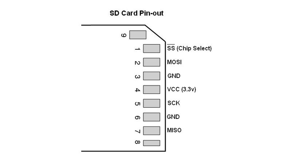
I had started this project with 1GB microSD card from SanDisk (later on tested with transcend cards also). The microcontroller is AVR ATmega8 or ATmega32 running at 8Mhz internal clock. MAX232 is used to interface the circuit with PC for monitoring the data. A 3.3v supply is used for powering the mega8, microSD and max232 (though the specified supply for max232 is 5v, it works comfortably at 3.3v).7 pins of the microSD are used here, shown in the figure of pin-out.
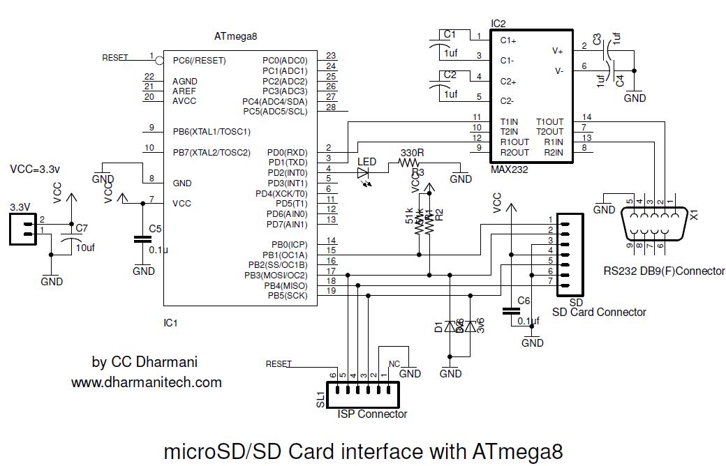
Schematic for ATmega8 is shown here (updated on 10 May 2010, SD series resistors are removed, as they were limiting the speed of SPI bus. 51k pullups are added on CMD/DAT lines. This gives better stability with different cards. Also, two 3.6v zeners are added to protect SD in case when the ISP programmer voltage levels are of 5v. these diodes are not required if your programmer has settings for 3.3v output)
(Note: VCC & GND pins of MAX232 are not shown in the schematic, but they must be connected in the actual hardware)
To continue reading click : SD/SDHC Card Interfacing with ATmega8 /32 (FAT32 implementation)
- Why is the microSD card a great option for embedded systems?
It is available very cheaply and offers huge memory. - How is the microSD card compatible with the system?
It is compatible with the SPI bus, making interfacing easy. - What microcontrollers are used in this project?
The project uses AVR ATmega8 or ATmega32 running at an 8Mhz internal clock. - Can the MAX232 work with a 3.3v supply?
Yes, although specified for 5v, it works comfortably at 3.3v. - Why were SD series resistors removed from the schematic?
They were removed because they limited the speed of the SPI bus. - What purpose do the 51k pullups serve?
They are added on CMD/DAT lines to give better stability with different cards. - When are the two 3.6v zeners required?
They are added to protect the SD if the ISP programmer voltage levels are 5v. - Are the zeners needed if the programmer has 3.3v output settings?
No, these diodes are not required if the programmer has settings for 3.3v output.
