Summary of Segway Robot with Accelerometers
This project details the design and construction of a two-wheeled self-balancing robot controlled via a Wii Nunchuck. Utilizing a PID control loop, the robot maintains stability by adjusting motor speed based on accelerometer data. The system employs an ATmega microcontroller, an L298N H-bridge for dual motors, and a LiPo battery, though wireless communication using nRF24L01+ transceivers was not successfully implemented due to noise issues.
Parts used in the Two-Wheeled Balance Bot:
- MMA8452Q Accelerometer
- L298N H-Bridge (Two units)
- Turnigy 2.2Ah 3S LiPo Battery
- RioRand LM2596 DC-DC Buck Regulator
- Linear Voltage Regulator (LDO) for 3.3V
- nRF24L01+ Transceiver
- Wii Nunchuk Controller
- ATmega16 Microcontroller (Controller side)
- ATmega644 Microcontroller (Robot side)
- Merke-Korff Gearmotors
- Plexiglas Chassis
Introduction
The objective of this project was to create a two-wheeled balance bot able to traverse a flat environment and adjust itself to shifts in position and weight, using a Proportional-Integral-Derivative (PID) feedback control loop to keep the robot upright. The balance bot is essentially a wirelessly controlled segway that leans its body forward and backward to correct the “error” in its position, if any.
Motivated by our intrigue in PID loops that were implemented in the tachometer and motor controller of lab 4 and desire to integrate the computing capabilities of mircocontrollers, we desired to design a mobile robot that required the use of a multi-dimensional PID loop. The result was an economical and amusing device that satisfied our desired goal.
High Level Design
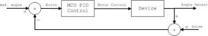
We decided to implement a Proportional-Integral-Derivative Controller (PID Controller) as the main feedback mechanism for our balance bot to self correct errors in acceleration. Because the axis of the accelerometer is parallel to the ground when the balance bot is upright, gravity, or deviations from the reference angle will register as acceleration and produce an error. This error is fed into the PID algorithm, and used to calculate the motor control parameters.
Consider the following PID equation:
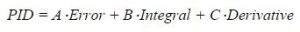
In our case, PID is the amount of swing the robot will move in order to eliminate the error. A description of each term is discussed below:
A*Error: This term is proportional to the current error value. If the robot is tilted one way, it compensates for the error and swings its body in a direction opposite to, but proportional to the error. This term is a direct feedback to the accelerometer. If the coefficient A becomes too large, the error correction becomes a positive feedback loop.
B*Integral: The contribution from the integral term is proportional to both the magnitude of the error and the duration of the error. This term fixes any accumulating error that compiles if the first term hasn’t already corrected it. Because the integral is an accumulation of past errors, the coefficient B can’t be too enormous, or else the robot will keep on adjusting for past errors even if it finally corrects itself.
C*Derivative: This term is proportional to the derivative of error. This term is used to predict future error and proactively adjusts the robot body to prevent that error. A massive C coefficient will result in a robot that is extremely sensitive to noise, and one that will make erroneous adjustments.
Rationale and Source of Our Project Idea
The inspiration for this idea came from a problem that occurs fairly often when racing custom built RC cars. When an RC car travels at high speeds and attempts to turn, it sometimes flips as a result of steering input, speed, and friction with the ground. Rollovers happen when cornering forces destabilize the vehicle. When a car makes a sharp turn, the centripetal force, inertial effects, and gravity all act on the car. Cornering forces from the tire act below the center of mass and push the car towards the center of the curve. Additionally, inertia acts horizontally through the car’s center of mass away from the center of the turn. Together, these two forces make the car gyrate towards the outside of the curve. The force of the car’s weight acts downward through the center of mass in the opposite direction. The car begins to turn over as the combination of the inertial and centripetal forces defeat the force of gravity.
We initially wanted to design a system that would combat these forces and prevent the rollover of an RC car, but opted for an easier idea, given the time and space constraints. Accelerating an RC car to speeds fast enough to result in rollover in a small lab classroom wouldn’t be possible and being forced to go outside to test our RC car after every incremental update would prove to be time consuming. After researching the past ECE 4760 Final Projects and browsing online, we decided to opt for a two-wheeled balance robot that mimics the movements of a segway. By having only two wheels, we limit the number of forces and thus degrees of freedom that we need to counteract with a PID loop.
Background Math
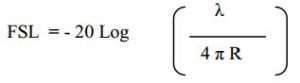
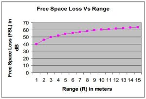
The accuracy of our results is based on a few metrics that quantify the success of packet transmission between RF transceivers. For the calculation of packet loss measurements, we make a transceiver transmit anywhere from 100 to 5000 packets. Because these packets have a known payload, the Packet Error Rate can be calculated at the receiver module. Free-space path loss (FSL) is the loss in signal strength of an electromagnetic wave that would result from a line-of-sight path through free space, with no obstacles nearby to cause reflection or diffraction. Figure # displays the equation used to calculate the FSL. Lambda is the wavelength at 2.4 GHz and R is the maximum theoretical line of sight range obtainable in meters.
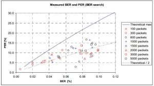
Moreover, Bit Error Rate (BER) is the number of received bits of a data stream over a communication channel that have been altered due to noise, interference, distortion or bit synchronization errors. Packet Error Rate (PER) is the number of incorrectly received data packets divided by the total number of received packets. The procedure for calculating the PER is as follows:
1. Transmit an RF signal from module 1 that the receiver can demodulate.
2. Vary the number of packets transmitted from module1 in a systematic approach.
3. Count the number of errors in the received packets at module 2.
4. Repeat steps 1-3 for a variety of distances and packets with different payloads.
Logical Structure
The balance bot is structured into three different stages: the wireless communication stage, the Proportional-Integral-Derivative Controller (PID Controller) stage, and the Pulse Width Modulation (PWM) stage. The context switch between stages is completed by the TinyRealTime kernel that allows several real time tasks to run simultaneously, with each task behaving as it were the only program running. The figure displaying the state transition diagram above reflects the flow of these states during normal operation. Each of these states represents events both in hardware and software and, will be further segmented into hardware and software components.
Our project contains two CPUs that effectively communicate with each other, the ATMega16 and ATMega1284. Wireless communication between the CPUs is accomplished by two nrf24l01+ transceivers. The ATMega16, along with a RF transceiver, is attached to the Wii Nunchuck to transmit directional commands to the second RF transceiver and ATMega1284 to receive and interpret commands for the balance bot. To achieve bi-directional motor control, a PWM signal rapidly oscillates the voltage applied to the motor. In conjunction with the PID Control loop and the accelerometer information, the balance bot moves with precision and effectively counteracts the current error in upright posture.
Hardware and Software Tradeoffs
We opted for the rather large 120x60mm offroad wheels instead of a pair of smaller wheels because a larger wheel and tire combination reduces the tire’s sidewall height. The sidewall is the distance between the outside and inner diameters of a tire, or the distance from where the tire meets the pavement to where the tire meets the wheel. Short sidewall heights improve handling, but deliver a harsher ride. Moreover, larger wheels raise the center of gravity of the robot and make the robot more sensitive to changes in position and weight. To demonstrate the ability of our robot to balance itself, it is advantageous to have an unsmooth ride and a high center of gravity. This ensures our robot will be continuously adjusting itself as it moves along a path.
Furthermore, we decided to use wireless communication to control the balance bot. In order to implement wireless communication, the nRF24L01+ transceivers were chosen. Adding two transceivers amplifies the level of complexity to the project because we now have to program and test the transceivers and debug them if anything doesn’t go as planned. For example, during the testing phase of this robot, we noticed that noise caused a huge issue in successful acknowledgment of a packet. Even after isolating the transceivers and removing ourselves from as much noise as possible, transmission errors still occurred. Only after perusing the datasheet of this component did we discover and comprehend the Enhanced ShockBurst (ESB) protocol to combat the noise issue. Enhanced ShockBurst is a protocol that supports auto acknowledgements and retransmission of packets to achieve reliable communication at the expense of reduced throughput.
On the opposite end of the spectrum, if we chose not to utilize the transceivers, our balance bot would be limited in range to the length of a wire connected to the Wii Nunchuck. Not only does tethering the controller make transport of our robot more difficult, but it also creates a safety hazard because a long length of wire is unrolled on the floor and easily able to be tripped over. Wireless communication extends the territory that our robot can traverse to 100 meters, and provides a polished look to our composition.
Standards
To implement communication between the PC, via PuTTY, and our microcontroller, we serialized data according to the UART standard. An integrated circuit connecting the serial port to the microcontroller implemented the RS-232 standard, which sets standards on pin configurations, as well as electrical characteristics and timing of signals. UART is useful for printing out status updates during the debug process. The nRF24L01+ transceivers and microcontroller communicate using the Serial Peripheral Interface (SPI) bus, an implementation that already existed in the drivers that we selected.
Relevant Copyrights
We didn’t obtain inspiration from commercial products for this idea, but later found out that there existed a smartphone controlled and gesture-driven robot manufactured by WowWee (MIP). It has analogous behavior to our robot, so patents that already exist for the MIP would be pertinent to extensions in our original design. However, an integral difference exists in the control mechanisms of MIP and our balance bot. MIP is controlled by fingertip gestures on a smartphone via Bluetooth and our robot is controlled by a Wii Nunchuck.
The Tiny Real time (TRT) and supplemental trtUart libraries are copyrighted under the very relaxed “Beer-Ware” license by Joerg Wunsch. There are no other relevant copyrights or trademarks that we know of.
Hardware
In order to create a wirelessly controllable segway robot there are several key hardware components that need to be utilized. There are as follows: (1) an accelerometer, (2) an H-bridge, (3) a battery, (4) a regulator, (5) a transceiver, (6) a remote controller, and finally (7) a microcontroller. Furthermore we needed to create the mechanical structure of the Segway Robot it self to house these electrical components.
Electrical Components
The MMA8452Q Accelerometer
In order to have a way of measuring the Segway Robot’s tilt we decided to use an accelerometer. The MMA8452Q accelerometer allows us to measure acceleration in three axes with 12 bit precision. The MMA8452Q runs at 3.3V however the board that we ordered from sparkFun has an onboard 3.3V regulator so that we can input the MCU’s 5V to power the accelerometer. The MMA8452Q accelerometer has I2C port in which we can communicate with. By reading from the I2C port we can get the Segway Robot’s acceleration data to the MCU and appropriately respond. The MMA8452Q provides an inexpensive way to get the necessary data in order to balance the robot.
The L298N H-Bridge
Another important facet of our design is the L298N H-bridge. An H-bridge allows us to drive a motor in either directon depending on input logic. The L298N has four input pins, four output pins, and two enable pins. Using the L298N we can drive two motors at the same time since it has two output channels. However since we are expecting high currents to be drawn from the motors and the L298 can only support up to 2 amperes from each channel we decided two use two L298’s to drive our two motors, each with their channels running in parallel. Running each individual L298 in parallel gives us a maximum current rating of 4 amperes for each L298, which is sufficient. We are able to control our motors by sending two logic pins and one PWM to each L298. Using the two logic pins we can specify which direction we want the current to flow through motor and by sending the PWM to the enable pin we can turn the output of the L298 as a PWM as well. Using the L298’s we can control how fast we want our motors to go as well as its direction.
The LiPo Battery
Due to the high power requirements of our system (up to 6A draw between the motors after the boost converter, which could result in transient peaks of 9A loads on the battery) we opted for a Li-Po pack, immediately settling for a 3S configuration (11.1V) as this would be a fair balance in terms of price and voltage requirements for our system. In general, high performance but affordable Lithium batteries are sold in the domain of RC car and airplane hobbyists, as this is a relatively large industry that has been around for decades. Runtime was an important consideration in our selection process, with hopes of achieving 45 minutes to an hour operation under usual conditions – at approximately 2A mean draw, this would yield a requirement of a 2Ah pack – relatively small, on the full scale of options available. We settled on a Turnigy 2.2Ah 3S pack from HobbyKing, a popular distributor of electronics for hobby uses, as it was very well reviewed yet perhaps the cheapest pack per capacity within its range.
The Voltage Regulators
Our original design called for 5V regulation for the microcontrollers and primary peripherals, 3.3V regulation for the tethered nunchuk and RF module, and a boosted voltage of around 20V for the primary drive motors (in order to increase their no-load speed to approximately 180 RPM), all from a single on-board battery supply. Once the battery was settled on as a 3S Li-Po 11.1V pack, it was clear a step-up switching regulator would be required for the high voltage motor line.
Linear LDO’s could have been used for both 3.3V and 5V, but with a drop of up to 7V down from a fully charged LiPo pack to the 5V rail, the losses in a linear regulator become non-trivial and for our mobile robot runtime was certainly a concern. We resolved to purchase an off-the-shelf DC-DC buck regulator from Amazon – a RioRand branded, LM2596 based board – as these are cheap, fully integrated regulation packages that perfectly fit our design specifications. This board was used to regulate 5V from the unregulated battery input, operating at much higher efficiencies than what would have been possible with an LDO. However, because the drop from 5V to 3.3V is relatively minimal, and the current draw by the 3.3V peripherals was also quite trivial, we were able to simply use an LDO for the 3.3V line and tap its input off the main 5V rail.
The addition of a high voltage boost converter for the actuators was a more involved process. We settled immediately on the MC34063 multi-purpose switching regulator from On Semiconductors, as we had some prior experience with it and in general it is a very popular choice for high-current boosting applications such as ours. Because the regulator itself is only rated for 1.5A, and we expected up to as much as 6A at stall between both motors, we needed to make use of an external switch circuit using the MC34063. We based our circuit off the work done by Kenneth Finnegan, shown below. The switching regulator was to be set at around 20V initially, so our feedback circuit was modified with the appropriate resistor values, with a generic logic-level nMOS used as the external switch. Our initial prototype of the circuit on a breadboard was successful, but unfortunately the circuit had last minute issues with wiring once it was soldered to a perf. board for installation on the robot, forcing us to leave the boost converter off completely and use the unregulated battery voltage directly for the high voltage motor rail.
The nRF24L01+ Transceiver
Nordic Semiconductor’s nRF24L01+ is an inexpensive transceiver capable of packet communication over long distances. The purpose of the radios are to provide the remote control a means of getting data to the Segway Robot. The nRF24L01+ radio is supposedly easy to use as it can communicate with an MCU through SPI. The nRF24L01+ radios that we ordred came on a breakout board in which we had access to power pins as well as its SPI pins. Using SPI we can configure the radio as well transmit and receive data.
The Remote Control
In order to provide the user a means of controlling the Segway Robot, we have designed a remote control. This remote control has three main components, the nRF24L01+, the ATmega16, and a Wii Nunchuk. We chose the ATmega16 for the controller because the code will not be very intensive and it provides everything that we need to do. To provide the user a familiar interface we decided to use a Wii Nunchuk. The Wii Nunchuk has a breakout that exposes the power and I2C pins. Using the I2C pins we can use the ATmega16 to communicate with the Wii Nunchuk to get the joystick values as well as its button and accelerometer values. Using the joystick values the user can send data to the MCU which in turn will then transmit it to the Segway Robot. Based on the information the Segway Robot receives it will know whether to turn left or right, move forwards or backwards, or remain still.
The ATmega644
To communicate with the all of these peripheral devices we chose the ATmega644. We chose the ATmega644 because it is very much like the ATmega1284 that we have been working on in lab however it just has less memory. Using the ATmega644 we have the means to control all of these peripheral devices whether it be over SPI, I2C, logic pins, etc. By loading up to correct software we have the means to control the Segway Robot in its entirety
Mechanical Design
Our mechanical hardware design methodology was primarily driven by two antagonistic factors – the limited $100 budget and a desire to create a quality robotic chassis for the task at hand. In order to achieve success with both criteria, a middle ground of practical minimalism was needed.
Because the budget was such a strict constraint, especially for a fully integrated mechatronic system such as this, we found it easiest to take care of all purchases first, with only a rough idea of our design in mind, in order to constrain our design space a bit further (to more manageable proportions) and make sure all required components would be on hand once the final design process began. In order to fit the budget, we limited our search to mainly third party resellers – eBay, All Electronics, Marlin P. Jones, etc. Combinations of the various part options available were studied for tradeoffs and the budget, shown below, was compiled as early in the design process as possible.
Perhaps the most crucial purchase decision made was the selection of the two drive motors. Our specifications required brushed DC motors, rated for approximately 12V with stall currents of 3A max, with no-load speeds around 100 RPM. Though torque requirements were not initially computed because of the many unknowns remaining in the design, it was expected a gear motor was necessary in order to optimize for low rotation speeds at high torques given the nature of this “inverted pendulum” layout. Unfortunately, secondary resellers hardly provide adequate specifications about things like electric motors, so the selection process was tedious and largely based on guess work and the hope that a given product photo will include a valid part number. We eventually settled on two repurposed Merkle-Korff gearmotors from eBay, as the seller was able to provide a mechanical drawing and electrical specifications ahead of time, allowing us to proceed with the design as we awaited the shipment.
Wheels were similarly found on eBay, though, naturally, they were far easier to select given their passive nature. Unfortunately, the seller did not advertise that these wheels had absolutely no spline or hub, forcing us to struggle with fixing the wheels to the motors’ drive shafts. We ended up finding some set-screw hubs of the perfect diameter and epoxying them to the wheels – a makeshift solution, but unfortunately the geometry simply did not allow for anything cleaner given the resources available to us.
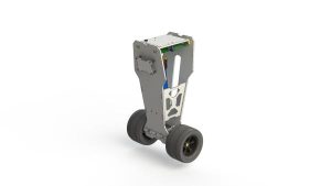
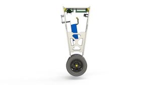
Once the off-the-shelf parts were all purchased, the actual mechanical design process was initiated. After considering a number of possible design directions during our initial brainstorming sessions, we settled on what later became our final design as it seemed to be our best bet of creating an aesthetically pleasing yet mechanically sound and financially feasible robot. The design, shown in the CAD renderings, could perhaps be described as a top-heavy trapezoid with a sagittal-plane symmetry. This orientation allows us to maximize the moment of inertia about the wheel axis by organizing most of the internal hardware (electronics, battery, etc.) toward the “head” of the robot and leaving the middle area empty, thereby optimizing for control authority when balancing.
The chassis consists nearly entirely of laser-cut Plexiglas sheet, with a few 3D printed couplings and the necessary fasteners – heat-set threading for the Plexiglas, matching screws, lock washers, and standoffs to create a metallic scaffold for the undercarriage holding the motors.
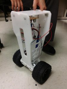
The final build, shown in the photos, was constructed without too many problems. Poor tolerances on the laser cut Plexiglas resulted in a few overly constrained components, but overall the structure feels rigid. Unfortunately, the weight of the drive system really dominates the entire structure, thus the center of mass is a bit lower than ideal. In future iterations, it may be necessary to stretch the body of the robot further up and possible artificially add weight to the head region in order to distribute the mass more appropriately. The tolerance issues could also be easily be taken care of with additional iterations that optimize manufacturability, but such processes are just a matter of time and resources.
Software
Our software can be broken up into four main sections, the accelerometer, the Wii Nunchuk, the transceivers, and the motor control. Their descriptions are as follows:
Accelerometer Code
To interact with the acceleromter we need to use an I2C (TWI) port. In order to setup the I2C on the ATmega1284 we decided to use Peter Fleury’s I2C library. In his I2C library we have the capability to initialize, read, and write all using I2C. Using this library provides an easy means to communicating with the accelerometer. First to test communications, we wrote code to test soley the accelerometer. Using the I2C protocol we found in the accelerometer’s datasheet we were able to communicate with the accelerometer. Using the test code we were able to read and write to the accelerometer and see the accelerometer’s measurements printed out over serial.
Wii Nunchuk Code
When writing code for the Wii Nunchuk we took a similar approach as we did with the accelerometer. We first wrote test code to test soley the Wii Nunchuk. Our code was designed to read data from the Wii Nunchuk and the print those readings to serial. While the Wii Nunchuk also communicates using I2C we were able to find another library online, written by Davide Gironi, that was specifically for communicating with the Wii Nunchuk. This library was also based off of Peter Fleury’s I2C library. When we first tried to communicate with the Wii Nunchuk we were not able to correctly read data from our Nunchuk. Upon debugging and further inspection we found that we had to put a five millisecond delay between writing and reading otherwise the read data would become corrupt. After implementing this delay we found the Wii Nunchuk to work perfectly.
RF Code
Again since our approach was working, we approached the RF code the same way. We found a library specifically for the nRF24L01+, written by Yi Heng Lee, and implemented code to test solely these transceivers. However this time we found that we could seem to get the code working. We tried several variations of the code but to no avail. We double checked to make sure that the SPI configuration on the ATmega1284 was correct and that the pins matched but we found that we were not able to communicate using these radios. Even one of our team members, Andre, wrote simple code using a tutorial he found online to communicate using SPI with the nRF24L01+ but with no luck (see my_nRF from the appendix). The nRF24L01+ showed no signs of functionality and to this day we do not know why we were not able to communicate with the nRF24L01+.
Motor Control Code
To control the motors we had to use two PWM signals, and four logic lines. Setting up these PWMs was much like the tachometer from Lab 4 and so we decided to recycle the motor control from the tachometer. Also from the tachometer lab we recycled the PID loop that we were using and redesigned it to fit the purposes of this project. Unfortunately we did not have the time to test this code, so we did not see whether it would work until we had put the Segway Robot together.
Putting It All Together
Now that we had written code for each of the key components it was time to put it all together. We decided to use TinyRealTime since it would help us better organize the code set task times. Originally we had decided to put each of the code pieces into different tasks but we realized that we would never want to update the PID loop without first from the accelerometer. Since we had each individual component working, putting the code together was easy since we knew what would work and what wouldn’t, with exceptions of the motor control task.
Results
Speed of Execution
The execution speed of our design is rather quick. By choosing to tether the Wii Nunchuck directly to the ATMega1284, the issue of latency was almost non-existent. The length of time it takes for the transmission of directional commands from the Wii Nunchuck to the microcontroller increases ever so slightly for every additional foot of wire the Nunchcuk is connected to. Luckily, the length of this wire is 4 feet and the time it takes the microcontroller to tune the PID loop according to the new parameters occurs on a millisecond scale. A millisecond lag is negligible and shouldn’t affect the quality of a user’s interaction with our balance bot.
Accuracy
Although we were unable to implement the nRF24l01+ transceivers, we did conduct a lot of research regarding its accuracy. These transceivers have a maximum range of 100 meters and increasing the distance between two RF transceivers increases the probability of noise and packet errors. Luckily, because our product is meant to be used within a home environment, the average distance that consumers use the balance bot is 30 meters, which ensures no significant noise disturbance.
To increase the percentage of successful packet transmissions, nRF24L01+ documentation recommends that send and receive addresses have multiple transitions between 1 and 0 bits to avoid noise being mistaken for packets. For example, an address such as 0xFFFFFFFFFF, or addresses where the level shifts only one time (i.e. 000FFFFFFF) can often be detected in noise and can give a false detection, which may lead to an increased Packet Error Rate (PER). PER is the number of incorrectly received data packets divided by the total number of received packets.
Before analyzing the figures below to quantify the various error measurements, here are some definitions of the terms used. As defined in “Standard Definitions of Terms for Antennas”, IEEE Std 145-1983, Free-Space Path Loss (FSL) is, “The loss between two isotropic radiators in free space, expressed as a power ratio.” Similarly, Bit Error Rate (BER) is defined as the number of bit errors divided by the total number of transferred bits during a studied time interval, expressed as a percentage.
Safety
A current of approximately 50mA and above across your heart can kill you. Under the right conditions, there is even enough current in a 9V battery to cause death. We ensured that all circuitry was as compact as possible and that all batteries and electrical connections were well separated to minimize the possibility of an electrical short. Also, our robot has an enclosed body that ensures no electrical components are in direct skin contact.
The default operating conditions assume this robot is on the floor. However, due to inclement weather, people may track water, snow, or mud onto the floor, which can cause issues to the robot. Further updates to this project can include waterproofing the robot body to prevent harming the user and/or electrical components.
Another possible risk is tripping on the robot if you are unaware of your surroundings. Unfortunately, this is an inherent risk with any device that can is placed on the floor and can become an obstacle in your path. The best resolution for this dilemma is to simply be more cognizant when walking.
Interference
Our RF transceivers operate on the 2.4GHz frequency band and have the potential to interfere with other wireless transceivers running on the same frequency. Because our product is meant for consumers in the home environment, the possibility that the balance bot is in the presence of other devices operating in this range, such as telephones, wireless routers, or microwaves is likely. However, this concern is fairly trivial because the nRF24L01+ transceivers will discard packets with an incorrect identification number, meaning that only the correct packets will be stored and processed. Lastly, during our project demo, no other groups present were using the same RF transceivers. Moreover, by enabling the Enhanced ShockBurst (ESB) protocol the noise issue was mitigated. Enhanced ShockBurst is a protocol that supports auto acknowledgements and retransmission of packets to achieve reliable communication at the expense of reduced throughput.
Usability
Our aim was to create a balance bot that mimicked a final product ready for mass production. Consumers of this product need not read a lengthy instruction manual to comprehend how to use this robot. Simply turn it on and use the controller to direct the robot. In case of drops and falls, all modules are mounted on and enclosed in plexiglass which provides a rugged build capable of shock absorption. The system is already relatively lightweight and compact and further improvements to the aforementioned features can only be obtained by substantially increasing the costs of components.
As far as the visual attractiveness of our product goes, the quality of the soldering slightly reduces this. We were limited by time constraints and the bulky soldering tips that didn’t produce an accurate solder joint. However, only under close scrutiny is this fault noticed and thus shouldn’t be considered. The ergonomics of our joystick are superior to other controllers on the market because we utilize the Wii Nunchuck, a controller that has been specifically tailored for the comfort of consumers, after years of research by the Nintendo team.
Conclusions
Final Thoughts
The outcome of our balance bot has satisfied our expectations. We created a functional balance bot that was sensitive to its own weight and position and adjusted itself in order to reach maximum stability. We gathered knowledge learned from coursework, not only in ECE 4760, but many previous classes and integrated them into a single product. Even though we weren’t able to implement wireless communication with RF transceivers, we were proud of our collaboration and working efforts to assemble and finalize code for this project in the limited time frame we had.
For future iterations of this project, we would like to ensure the capability of traversing a non-flat, or sloped terrain. At this point in time, we only guarantee the robot’s capacity to travel on flat surfaces. This can be done by further tuning the PID loop, acquiring a different set of wheels that are resistant to changes in topography, or obtaining a more powerful motor. Additionally, we can add an assortment of functions to the balance bot, such as the definition of macros or the increase/decrease of speed. In order to use these new features, we will need to map the unused buttons on the Wii Nunchuck to realize these capabilities. If the inclusion of these new elements clutter the current joystick, a more advanced joystick such as the Xbox 360 controller can be adapted. As discussed in the Usability section, a greater allotment of time will allow us to either solder joints slowly to achieve a more professional look, or invoke the use of automatic wave soldering machines to produce a flawless solder joint. Another way that we can improve the look of our robot is to add minor mechanical revisions to the design of our robot body. At this point in time, the interlocking joints of the robot body are very tight and produce a visible strain that contorts the body and skews the wheels to an angle above parallel. A further way of reforming the looks of the robot includes swapping out the carelessly soldered boost convertors that were crafted under serious time constraints and minimal PCB layout planning. We are under the $100 budget and could afford to replace our hastily created boost convertor for a commercial product.
Lastly, we’d love to actually utilize a set of RF transceivers to enable wireless communication. Because the nRF24L01+ transceivers have given individuals a great deal of noise issues, we plan to obtain RF transceivers with a greater range and more efficient noise reduction to increase the overall quality of this product. By incorporating improved RF transceivers, there is a decreased chance of commands not being received and a possibility of expanding the consumer base to enthusiasts who compete with these vehicles that wouldn’t have been able to do so with the limited range.
Did Our Design Conform to Standards?
To aid the debugging process, we complied with RS-232 standards, defined by the Electronics Industries Association (EIA), to allow communication between the microcontroller UART interface and a terminal emulator on a computer.
Intellectual Property Considerations
The information used to create this project was knowledge learned from previous classes taken at Cornell University, component datasheets provided by the component manufacturers, the Exhibition section of the online Arduino forums, and the “YBot – Balancing Arduino Robot” blog post on the Let’s Make Robots! website.
The motivation for this project and initial hardware design can be attributed to a blog post submitted on the Let’s Make Robots! website by Dallaby and an online forum post in the Arduino forums by an individual with the username, “Kas.” Their work and preliminary code gave us a good understanding of what we needed to do to properly interface the MCU with the accelerometers.
The software section of our project was a combination of several libraries. The Tiny Real Time (TRT) library allows many real time tasks to run concurrently, with each task behaving as if it were the only program running. This allows the MCU to context switch between real-time tasks. This library was written by Dan Henriksson and Anton Cervin, but modified by Bruce Land exclusively for the ECE 4760 course. Additionally, trtUart facilitated the debugging process of our device while developing our code and hardware. This library was written by Joerg Wunsch to allow for UART communications with a microcontroller utilizing the TRT kernel.
Moreover, the communication between the nRF24L01+ transceivers was accomplished using the drivers written by Yi Heng Lee. Lee provides an API that automatically takes care of many pin configurations and has functions to create packets in a simplistic manner. Additionally, Davide Gironi created the library that allows us to access the joystick and accelerometer values from the Wii Nunchuck Much like Lee’s API, this library also includes functions to make interfacing with the Wii Nunchuck an easy process.
Finally, to design this website, we adapted a template for the website from the Spring 2010 project, Human Tetris, by Adam Papamarcos and Kerran Flanagan. Their project website is included in the references section of this site. The patents listed previously are only related to our project and we did not directly use any of the ideas claimed within them. Our final design is a collaboration of previously written code and design concepts from a variety of sources, so we don’t own the intellectual property regarding the implementation of a self-balancing robot. We did not reverse-engineer a design, so there are no patent or trademark issues. We did not have to sign any non-disclosure agreements for sample parts. As of right now, we have not considered the possibility of any patent or publishing opportunities.
Ethical Considerations
The IEEE Code of Ethics was rigorously adhered to throughout our prototype design. Specifically, there were two aspects of the code that resonated with our team. First, bullet point seven of the code states, “to seek, accept, and offer honest criticism of technical work, to acknowledge and correct errors, and to credit properly the contributions of others.” This was pertinent to us during the initial planning stages of the final project when discussing each element of our design with Bruce Land and the TAs. We initially overestimated the amount of time each of us were able to contribute and proposed a project with many more features than we have time to implement. Thankfully, speaking with Bruce Land and the TAs leveled our amibtions and forced us to rethink about what was actually possible during the time period we were given. Originally, we wished to give our robot the ability to balance upon uneven and sloped terrain, but scaled this capability back to only include flat terrain. Second, bullet point three states, “to be honest and realistic in stating claims or estimates based on available data.” This was relevant to us when composing the final website writeup and the preparing for the project demo. Due to the enormous amount of interference present in the lab setting, the RF modules that transmit the Wii Nunchuck commands to move the robot are limited in distance. According to the datasheet specifications of the nRF24L01+ transceivers, the range is supposed to be 100 meters. By testing the range of the transceivers, we concluded that while these components may be able to communicate at the aforementioned range, it definitely isn’t without significant noise disturbace and can operate without momentous amount of noise within a range of 20 meters. Moreover, our balance bot’s mobility was limited due to the large wheel size that was chosen. The turning radius of our robot is enormous and adeptly roaming an evironment is tricky, especially an environment with the existence of obtacles. As moral engineers who wish to remain truthful during all aspects of our writeup and demo, we didn’t lie about any non-working components of our balance bot and noted the flaws that existed, i.e. limited range and mobility. The IEE Code of Ethics was a powerful collection of rules that significantly impacted the creation of our robot.
Legal Considerations
Our project, to our knowledge, doesn’t violate any legal regulations. As a disclaimer, please note that users should advertise caution when using this robot amongst young children. Kids might be able to break a piece off of the robot body and attempt to eat it. Additionally, our project doesn’t emit any excessive EMF or sound. The RF transceivers that we planned to use function on the same 2.4GHz frequency that wireless routers and telephones operate on and will not provide any more harm than these devices already do to an individual. Lastly, some components of our design were based on source code that is freely available for personal and/or educational use, so there is no violation of intellectual property theft.
Appendix
A. Schematic
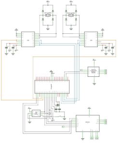
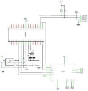
Source:
- How does the balance bot correct its position?
The robot uses a PID feedback control loop where the accelerometer detects tilt errors, which are fed into the algorithm to calculate motor control parameters. - What is the purpose of the integral term in the PID equation?
The integral term fixes accumulating errors that compile if the proportional term has not already corrected the error. - Why were larger offroad wheels selected for the robot?
Larger wheels were chosen to reduce sidewall height for better handling and to raise the center of gravity, making the robot more sensitive to position changes for demonstration purposes. - Can the robot traverse non-flat terrain?
No, the current design only guarantees capacity to travel on flat surfaces. - What protocol was discovered to combat noise in the RF transceivers?
The Enhanced ShockBurst (ESB) protocol supports auto acknowledgements and retransmission of packets to achieve reliable communication. - Why did the team fail to implement wireless communication with the nRF24L01+?
The team could not communicate using the radios despite checking SPI configurations and trying various code variations; the reason remains unknown. - How is the Wii Nunchuk connected to the microcontroller?
The Wii Nunchuk communicates with the ATmega16 via I2C pins after a five-millisecond delay is implemented between writing and reading to prevent corrupt data. - What voltage configuration was used for the LiPo battery?
A 3S configuration (11.1V) was settled upon as a fair balance between price and voltage requirements.