Summary of Some Assembly Required
The article details the creation of an autonomous robot built from a Venom RC car, controlled by an Arduino Uno using AVR Assembly. The system utilizes IR sensors for obstacle detection and PWM signals to manage steering and speed. The code implements three behavioral modes: full-speed forward, turning away from obstacles, and a "panic mode" involving backing up when objects are too close. The project highlights low-level hardware interaction, timer configuration for 50Hz PWM, and software-based sensor averaging.
Parts used in the Autonomous Robot:
- Venom RC car
- Arduino Uno (ATMega328p microcontroller)
- IR range-finding sensors (two units)
- Servo motor (steering)
- Electronic speed control (ESC)
- WinAVR toolset
- Emulare AVR emulator
What We Did
We created an autonomous robot that explores the world in linear trajectories while avoiding obstacle using IR range-finding.
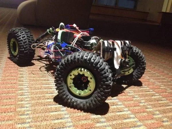
The robot is a Venom RC car altered to be controlled by an Arduino Uno programmed in AVR Assembly (a very low-level programming language specific to the type of hardware used). The Arduino communicates to the hardware system (both the sensors and motors) using PWM (Pulse Width Modulation), a protocol often used to control servos and in Remote Control. To sense the world, there are two IR sensors mounted on the front of the robot to determine the proximity of obstacles in its path and determine the best direction to turn to avoid them.
When there are no obstacles around the robot, it goes full-speed directly forwards. When it senses an object, it slows down and turns away. If the object gets too close, the robot enters an “OHMYGOODNESSIMGOINGTODIE” panic mode, stops, backs away from the object, and continues on its merry-way.
Why We Did It
We chose to do our project mostly robots are awesome, and we wanted a derpy robot to play with. While we’d worked with MIPS assembly in class, working with an Arduino pushed us to get experience in the very different AVR Assembly. Working with a robot was an excellent way to experience working with hardware on a very low-level.
How We Did It
“This portion can assume an audience that has taken Computer Architecture, but don’t get burdened oby buzzwords. A sure sign of a bad engineer is over reliance on acronyms.”
Code Description
print "Hello world"
run robit --wallAvoid=True --becomeSkynet=False
PWM
The steering servo and electronic speed control both work off of standard 50 Hz Remote Control PWM signals. The pulse ranges from 1 ms to 2 ms, with ~1.5 ms being the neutral position. For servos with larger ranges, you might see pulses between 0.5 and 2.5 ms (neutral will still be around 1.5 ms).
From the perspective of the car: straight forward is pulse-width 1472 microseconds, full right (~45 degrees) is pulse-width 956 us, full left (~45 degrees) is pulse-width 1884 us. Throttle is more straightforward with a 2 ms pulse signalling full throttle forward, 1.5 ms signalling neutral (or braking, depending on settings), and 1 ms signalling full reverse.
While the ATMega328 has built-in PWM support, it only supports fairly high frequencies. Ones much, much faster than the 50 Hz our car is expecting. To implement slow PWM we need to use some features of the AVR’s timer/counter system. For a positive PWM we hold a signal high for one count (the pulse), then hold it low for the remainder of the 20 ms period before starting over.
AVR Timers
The Atmega 328p on our Arduino has 3 internal timers (0, 1, and 2). Timers 0 and 2 are 8-bit timers, Timer 1 is a 16-bit timer. Settings are controlled by writing to the Timer Counter Control Registers (TCCRx, x=0,1, or 2).
Frequency is controlled partly via a prescaler, an integer which divides down the maximum frequency (16 MHz)–so the minimum non-zero prescaler of 8 makes the timer run at 2MHz, while a prescaler of 64 reduces the timer to 256KHz.
Timer 1 is a 16-bit timer with the option to run in compare mode, allowing us to trigger events much lower frequencies. This is useful for working with 50Hz RC PWM. In compare mode, the AVR will compare the number of timer counts to the value loaded in the Output Compare Register (OCR) and perform various operations when they match. This can generate square waves, control PWM, or generate interrupts. TCCR1A and TCCR1B is outlined below but the behavior is analogous for Timers 0 and 2. Bits which are not described were not used in this project but are described in the resources linked at the end of this page.
| TCCR1A: | ||||||||
| Bit | 7 | 6 | 5 | 4 | 3 | 2 | 1 | 0 |
| Name | COM1A11) | COM1A02) | COM1B13) | COM1B04) | FOC1A5) | FOC1B6) | WGM117)) | WGM108)) |
| Initial value | 0 | 0 | 0 | 0 | 0 | 0 | 0 | 0 |
| TCCR1B: | ||||||||
| Bit | 7 | 6 | 5 | 4 | 3 | 2 | 1 | 0 |
| Name | ICNC19) | ICES110) | – | WGM1311)) | WGM1212)) | CS1213)) | CS1114)) | CS1015)) |
| Initial value | 0 | 0 | 0 | 0 | 0 | 0 | 0 | 0 |
| COM1xy effects: | ||
| COM1x1 | COM1x0 | Description |
| 0 | 0 | Normal Port Operation (The timer doesn’t change the voltage on the i/o pin) |
| 0 | 1 | Toggles OC1x16) on match |
| 1 | 0 | Clears OC1x17) on match–set level Low (GND) |
| 1 | 1 | Sets OC1x18) on match–set level High (VCC) |
| CSxy effects: | |||
| CSx2 | CSx1 | CSx0 | Effect |
| 0 | 0 | 0 | Timer stopped. |
| 0 | 0 | 1 | Clock = normal CPU frequency (FCPU) |
| 0 | 1 | 0 | Clk = FCPU/8 |
| 0 | 1 | 1 | Clk = FCPU/64 |
| 1 | 0 | 0 | Clk = FCPU/256 |
| 1 | 0 | 1 | Clk = FCPU/1024 |
| 1 | 1 | 0 | External Clock source on pin T0. Clock on falling edge. |
| 1 | 1 | 0 | External Clock source on pin T0. Clock on rising edge. |
The TCNT1 port holds the current value of Timer Counter 1, divided into two 8-bit ports TCNT1H (holding the high byte) and TCNT1L (holding the low byte). This is compared to the 16-bit value stored in the Output Compare Registers (OCR1A and OCR1B for timer 1), OCR1xH and OCR1xL. WGMxy determines the effect on match. Options vary between processors, but for our purposes we only care about Clear Time on Compare (CTC) which will reset the timer to zero on a match.
| CTC: | |||
| WGM13 | WGM12 | WGM11 | WGM10 |
| 0 | 1 | 0 | 0 |
The Timer Counter Interrupt Mask (TIMSK) is useful for more complicated timed operations, but all we need it for is to disable interrupts. This is done by clearing the register (filling it with 0s).
Sensor Processing
To decide how to react to the world determined to prevent the little robot from finding true freedom, the code samples from two analog input pins that are the signal wires to two IR sensors. The sensors are spaced apart and mounted on the front of the robot. In this way, the robot can determine how far away obstacles are, and determine how to turn from the side further way for more intelligent decision making.
Unfortunately, but not surprisingly, the sensors are very noisy fellows and require a lot of averaging to get any resemblance of smooth behavior. The documentation above specifically warns against adding a capacitor between the signal and ground or VCC, so an RC low-pass filter is inadvisable. We could get around that by filtering in another way, but this is a CompArch project, so we will do this in software! Arg! Therefore, we uses a simple rolling average of the last sixteen points. We discarded the use of an exponential rolling average due to the problems of floating point multiplication (sadness). Since the CPU is running many thousands of times faster than the sensor is providing new data (about 40ms), we make sure to only average distinct values.
Taking an average of several values is obnoxious in AVR assembly, as eight bits is not enough for the sum of even two sensor values. We stored a 16 bit sum in two 8-bit registers and carefully took the carry into account while adding. Dividing before adding could allow us to work entirely within 8 bits, but would destroy precision.
Based on the values from the sensors, we have three modes:
1. WHEEEEEEEEEEEEEEE!
2. Hmmmmm, a wall. I should probably avoid that.
3. OHMYGOODNESSAWALL. Panic! Beep!Beep!Beep! Honk.
In the “WHEEEEEEEEEE!” mode, the sensors are reading values below about 40 (meaning nothing is within about 45 cm), and the robot goes full forward in a strait trajectory. When the car gets to an obstacle less than 45 cm away, it goes into “Hmmmmm, a wall. I should probably avoid that,” where the car turns towards the higher of the two values (towards the direction with the further away obstacle). If either of the values drop below about 10, then an obstacle is less than 700mm away, and the robot enters “OHMYGOODNESSAWALL. Panic! Beep!Beep!Beep! Honk.” mode. In this mode, the robot turns towards the closer side of the obstacle and backs away until the robot is far enough away to successfully go to mode 2 without immediately losing its shit again. Unfortunately, we did not fully implement the third mode. Instead the car backs up just enough to lose its shit again. It does, however, eventually make its way out of the panic mode through this oscillation.
Code
We started our work with Assembly by simulating basic code in the Emulare AVR emulator. Once we were confident in our toolset we moved on to almost exclusively running code on the Arduino. We used the WinAVR toolset to build our code.
The basic architecture of our code is simple: we have a main loop that runs forever, reading samples from the ADC, averaging them, and then acting on the average. The snippet below shows the essence of our code, with some details removed.
main:
    call pwm_init
    call adc_enable

    ; ... (More initialization) ...

    .loop:
    ldi R24, 1       ; R24 = adc_read channel
    call adc_read    ; R24 = adc_read voltage read
    mov R25, R24
    ldi R24, 0       ; R24 = adc_read channel
    call adc_read    ; R24 = adc_read voltage read


    call add_sample
    call get_average ; R24 = adc rolling average for A0
                     ; R25 = adc rolling average for A1

    call evaluate
    call choose_steer_angle
    call choose_speed

    rjmp .loop
Our current build is comprised of two files, robit.S and data.S. These contain our actual logic and definitions of data locations in memory, respectively.
Gotchas
Register weirdness
Not all registers are created equal. For whatever reason Registers R0 through R15 cannot load immediate values. Only the Registers R16 through R31 can be set to an immediate value through the LDI command. The following commands are restricted to Registers R16 and above:
-
ANDI Rx,K: Bit-And of register Rx with a constant value K
-
CBR Rx,M: Clear all bits in register Rx that are set to one within the constant mask value M
-
CPI Rx,K: Compare the content of the register Rx with a constant value K
-
SBCI Rx,K: Subtract the constant K and the current value of the carry flag from the content of register Rx and store the result in register Rx
-
SBR Rx,M: Set all bits in register Rx to one, that are one in the constant mask M
-
SER Rx : Set all bits in register Rx to one (equal to LDI Rx,255)
- SUBI Rx,K: Subtract the constant K from the content of register Rx and store the result in register Rx.
- How does the robot avoid obstacles?
The robot uses two front-mounted IR sensors to detect proximity and turns toward the side with the higher reading to avoid collisions. - What programming language was used for the project?
The robot is programmed in AVR Assembly, a low-level language specific to the ATMega328p hardware. - Can the robot operate without PWM signals?
No, the steering servo and electronic speed control rely on standard 50 Hz Remote Control PWM signals to function. - What happens when an object is less than 700mm away?
The robot enters a panic mode where it backs away until it is far enough to resume normal avoidance behavior. - How did the developers handle noisy sensor data?
The team implemented a software-based rolling average of the last sixteen points instead of using physical capacitors. - Why was Timer 1 chosen for PWM generation?
Timer 1 is a 16-bit timer capable of running in compare mode, which allows for generating the slower 50 Hz frequency required by the car. - Which registers can load immediate values in AVR Assembly?
Only Registers R16 through R31 can be set to an immediate value using the LDI command. - What are the pulse widths for full left and full right steering?
Full right corresponds to 956 microseconds and full left corresponds to 1884 microseconds.