Summary of Spin Bike Controller
SmartSpin2K is an open-source DIY module that automates spin bike resistance by converting BLE signals from cycling apps into physical knob rotation via a stepper motor. It also functions as a BLE multiplexer, heart rate to watt converter, and protocol bridge using an ESP32. The project enables smart trainer capabilities for standard bikes and power meters through a combination of 3D-printed parts, electronics, and custom software.
Parts used in the SmartSpin2K:
- ESP 32 Dev Board
- NEMA 17 Pancake Stepper
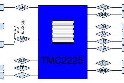
- TMC2225 Driver
- LM2596 Buck Converter
- 24V Power Supply
- Tactile Switches
- 608 Skate Bearings
- Power Meter (Optional)
- Custom PCB
- 3.5mm stereo headphone connector
- 5.5mm x 2.1mm DC power connector
- M3 x 8mm machine screws
- #6 x 3/4" stainless wood screws
- #4 x 1/2" flat head screws
- Stereo RCA to 3.5mm headphone y cable
- PETG or ABS filament
- TPU filament
- Hot glue
- Recom R-78E5.0-0.5 Voltage Regulator
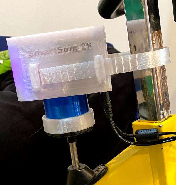
SmartSpin2K is an open hardware and software DIY module that converts BLE signals from a cycling APP (like Zwift, FulGaz, RGT, Sufferfest, etc.) and uses the information they broadcast to increase and decrease resistance on a spin bike by rotating the resistance knob with a stepper motor. SmartSpin2k receives BLE signals from common cycling peripherals such as HRM, power meters, and fitness bikes to rebroadcast BLE as a single stream to your chosen device. The system allows full smart trainer functionality with a simple spin bike and power meter.
Optionally, the SmartSpin2K project has also progressed to the point of where it’s useful without the hardware as a BLE device multiplexer, heart rate to watt converter (estimator), and proprietary BLE device to normal FTMS protocol converter using only the readily available ~$6 ESP32 devkit.
More information, updates, discussion, cad files and software are located at the project github: https://github.com/doudar/SmartSpin2k/
Check out the build guide for a non PCB SmartSpin2k here!
Supplies:
- ESP 32 Dev Board https://amzn.to/2ZNyjQX
- NEMA 17 Pancake Stepper https://amzn.to/37mKKHh
- TMC2225 https://amzn.to/3kctdEQ
- LM2596 Buck Converter https://amzn.to/33ofggY
- 24V Power Supply https://amzn.to/3r4e1i0
- Tactile Switches https://amzn.to/33ezmKx
- 608 Skate Bearings https://amzn.to/3isBzrW
- Power Meter(Optional so you can use it for fitness) https://amzn.to/3ioSjk7 (compatible with most pedals, some crank based meters
- The PCB from https://www.pcbway.com/project/shareproject/SmartSpin2k_PCB.html
Additional shop items
- 3.5mm stereo headphone connector
- 5.5mm x 2.1mm DC power connector
- (4) M3 x 8mm machine screws
- (4) #6 x 3/4″ stainless wood screws
- (4) #4 x 1/2″ flat head screws
- Stereo RCA to 3.5mm headphone “y” cable (used for shifter wiring)
- Hot glue
Step 1: Print Parts
PETG works well for all parts except the shifter straps. ABS will also work well.
Shifter straps need to be TPU.
Can also make shifters using other buttons. First version was just buttons covered in electrical tape and they worked okay.
You can find more information as well as the .stl files for the parts over at the projects github repository: https://github.com/doudar/SmartSpin2k/tree/master/Hardware
Step 2: Build Wire Harnesses and Install Into the Case.
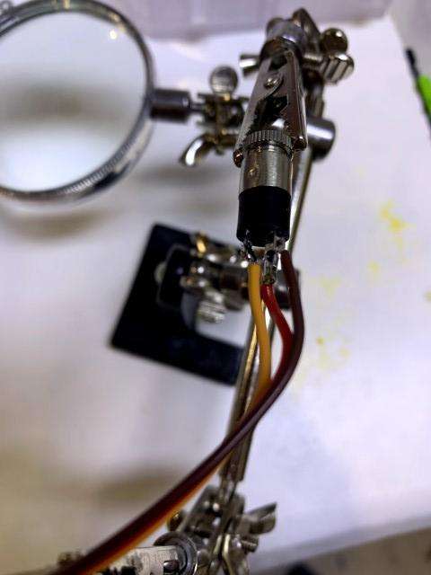
For the shifters, use a 3.5 mm headphone barrel connector for on one end and a 3 pin female connector on the other end. The longest wire is the common ground for the shifters.
Connect your power wires to a two pin connector on one end and to a female barrel connector (5.5mm x 2.5mm DC connector) that matches the 24V power supply. The wire harnesses should be 15-18 cm long. Make sure that the center connector is the positive wire. The positive pin on the PCB is the one closest to the edge of the board (and marked on the silkscreen).
Step 3: Install Gear and Crossbar Onto Stepper
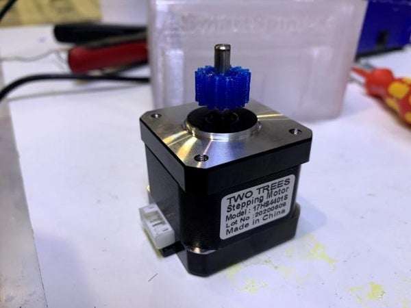
Press plastic gear down onto stepper driveshaft. Secure crossbar to stepper motor with two allen head screws sized M3 by 8mm.
Step 4: Solder PCB
Do NOT solder ESP32 and PCB together until ALL other components have been soldered to the PCB. Follow notes on PCB silkscreen for location and info on components. In testing, the board works with a wide range of capacitor values as the regulator we’re using is robust.
The most important aspect is to make sure the one on the input side is rated at double your supply voltage (use a 50v rated capacitor).
The other capacitors only need to be rated at 10v (5v circuit) and are much easier to find.
The resistor needs to be a 1/4w 1k Ohm.
The voltage regulator is a recom R-78E5.0-0.5 https://www.mouser.com/ProductDetail/recom/r-78e50-05/?qs=JeAkOuORR2UvBuiB2kZVZQ
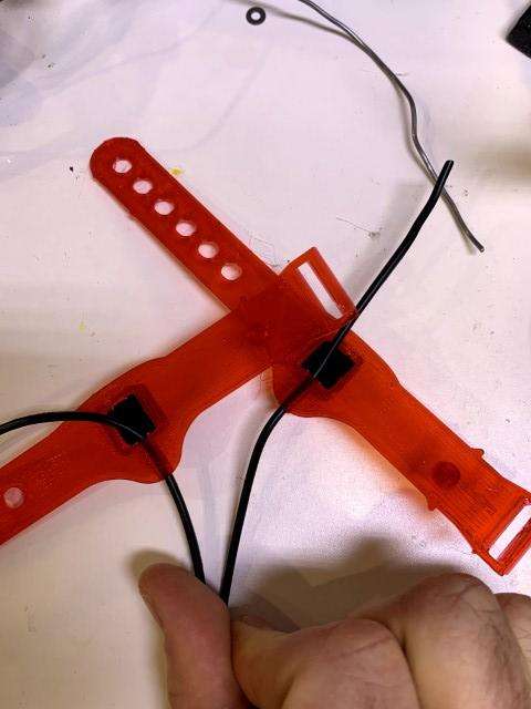
I’ve found that cutting the RCA plugs off of a 3.5mm to stereo RCA “Y” adapter cable is the easiest (and cheapest) way to make this cable.
Use a cable which is long enough to reach from your shifter location to your SmartSpin2k. Place push buttons into shifter housing, solder as indicated in the photos (so wires are diagonal to each other).
Trim the little square back cover so it fits easily into the back of the strap.
Add a fair amount of hot glue to the back of the button. Immediately put the back cover into position and (while the glue is still hot), depress the button numerous times to get a good button feel from the shifter.
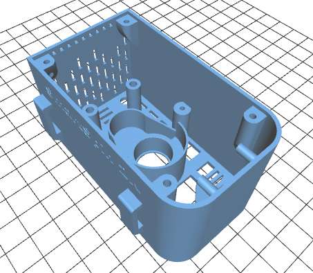
Step 6: Press Bearings Into Case
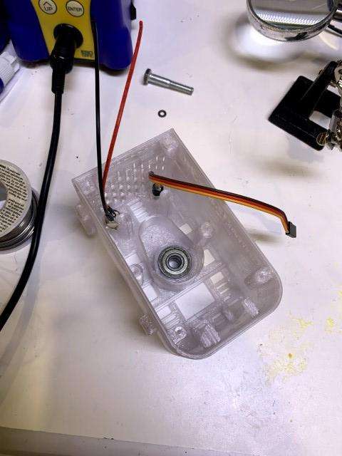
Two bearings are pressed into the case. Make sure they are flush with the bottom of the case on the outside. You may need to do a small amount of sanding on the case so the bearings fit smoothly, but don’t sand too much as we’re relying on a nice “press fit” for retention.
Source: Spin Bike Controller
- What does the SmartSpin2K module do?
It converts BLE signals from cycling apps to rotate a stepper motor that adjusts spin bike resistance. - Can I use this project without the hardware?
Yes, it can function as a BLE device multiplexer, heart rate to watt converter, and FTMS protocol converter using only an ESP32 devkit. - Which 3D printing materials work best for the parts?
PETG works well for most parts, while TPU is required specifically for shifter straps. - How should the capacitors be rated for the voltage regulator?
The input capacitor must be rated at double your supply voltage (e.g., 50v), while others need only 10v ratings. - What type of power supply is recommended?
A 24V power supply is used with a 5.5mm x 2.1mm DC connector matching the center positive pin. - How are the pushbuttons installed in the shifters?
Push buttons are placed in the housing with wires soldered diagonally, secured with hot glue and a trimmed back cover. - Does the system support existing fitness peripherals?
Yes, it receives BLE signals from HRMs, power meters, and fitness bikes to rebroadcast them as a single stream. - Where can I find the STL files for the printed parts?
The .stl files are available in the Hardware folder of the project's GitHub repository.