Summary of Starting AVR 8-bit Development
This tutorial explains setting up an AVR development environment using Atmel/Microchip Studio, AVRISP mkII programmer, and an ATtiny2313 on a breadboard to build and program a blinking LED. It covers required hardware and software, installing drivers, building the circuit, writing and compiling a simple C blink program, using Device Programming in Atmel Studio to read target voltage and device signature, and flashing the compiled HEX to the microcontroller to verify LED blinking.
Parts used in the attiny2313_blink:
- Electronic breadboard
- Single core single stranded wire
- 5V power supply
- AVRISP mkII programmer from Atmel
- ATtiny2313 microcontroller, DIP (ATtiny2313-20PU)
- 10k resistor, 1/4W, 5%
- 470 ohm resistor, 1/4W, 5%
- LED, through hole mounting
- 100n capacitor
This tutorial will guide us through acquiring the necessary tools and setting up our environment for C programming and embedded development using 8-bit AVR microcontrollers.
Specifically, it will cover:
The tools required for AVR development using the free Atmel Studio IDE on Windows.
Building a simple circuit with an AVR microcontroller and flashing LED.
Writing a basic C program and loading/running it on the AVR microcontroller board.
By completing a LED blinking sample project, we will learn the workflow for developing, compiling, and programming AVR chips – giving us the foundation to begin building more advanced embedded applications.
Let’s get started by exploring the toolchain and setting up our development workspace so we can begin programming our first AVR microcontroller!
Hardware Requirements
To program an AVR microcontroller, we need a USB programmer to load code onto the chip. This tutorial will utilize the AVRISP mkII (ATAVRISP2) programmer from Microchip. Equivalent USB programmers compatible with the AVRISP mkII standard will also suffice.
For our test circuit, we will construct a breadboard implementation around the low-cost ATtiny2313 microcontroller. A PC power supply will provide the necessary 5V power rail.
In addition to the microcontroller, the circuit will include an LED and current-limiting resistor. Single-strand hookup wire will connect the breadboarded components to the programming interface of the AVRISP mkII programmer.
By following the step-by-step instructions, we will assemble the hardware and have everything needed to begin developing our first AVR-based embedded applications.
Tutorial parts list:
- Electronic breadboard
- Single core single stranded wire
- 5V power supply
- AVRISP mkII programmer from Atmel
- ATtiny2313 microcontroller, DIP (ATtiny2313-20PU)
- 10k resistor, 1/4W, 5%
- 470 ohm resistor, 1/4W, 5%
- LED, through hole mounting
- 100n capacitor
Software Requirements
To get started with our development environment, we will need to acquire the Microchip Studio integrated development environment (IDE). This can be downloaded directly from the Microchip website.
Alternatively, older versions of Atmel Studio that are compatible with AVR microcontrollers can be found in Microchip’s archives.
This tutorial utilizes Atmel Studio version 6.0, though other recent releases should work similarly. The IDE will be installed on a system running Windows 7.
By obtaining the appropriate version of Microchip/Atmel Studio for our operating system, we’ll have the main tool needed to write, build, and debug AVR programs before loading them onto our target hardware.
Install the Software and AVRISP Programmer
Now that we have downloaded Atmel Studio, the next steps are:
Run the executable installation file to complete the setup of the Atmel Studio Integrated Development Environment (IDE) on our computer.
Once installation is finished, plug the AVRISP mkII programming device into a free USB port on the PC.
The drivers required to interface the AVRISP mkII with our system should automatically be detected and installed.
By guiding the installation process and ensuring our hardware is correctly connected via USB, we will set the stage for Atmel Studio to communicate with the AVR microcontroller programmer.
This will allow us to develop code on the PC before downloading it to physical boards using the AVRISP mkII.
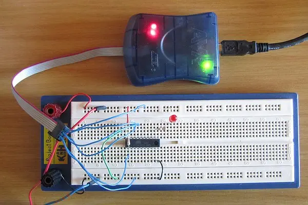
Building the Circuit
The circuit diagram is shown below:

The next step is to construct the circuit on a breadboard using the following components:
ATtiny2313 microcontroller
LED
Current-limiting resistor
We will then use single-strand hookup wire to connect the:
ISP header pins on the ATtiny2313 chip to
The corresponding pins on the AVRISP mkII programmer
By following the circuit diagram, we can properly interface the AVRISP mkII to the ATtiny2313 microcontroller built on the breadboard.
This will allow us to program and debug code on the physical chip using the connections between the breadboarded circuit and the USB programmer.
Let’s now assemble the hardware and verify all necessary connections are securely in place.
This photo shows the result:
Using Atmel Studio to Write the Program
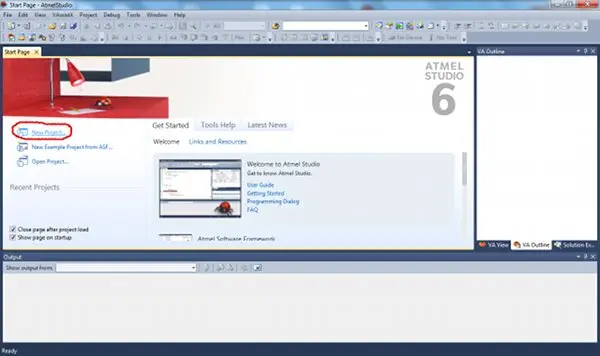
1. Start Atmel Studio.
2. Click New Project… from the Start Page window, or click File → New → Project…
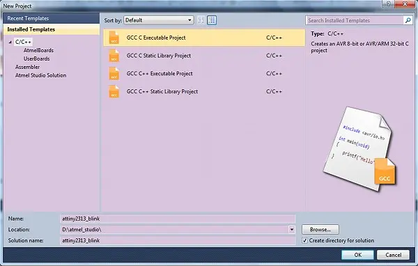
3. Select the location on your computer to save the project files. Also assign a name for the project.
For this tutorial, we will call our project “attiny2313_blink” and save it to an appropriate folder location.
When prompted, be sure to enter this name “attiny2313_blink” into the “Name” field, not the “Solution name” field.
The project name will identify our work specifically for the ATtiny 2313 microcontroller blinking LED sample code. Setting both the save location and unique name now allows us to easily identify and retrieve this project going forward.
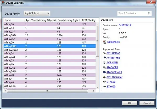
4. After naming the project, a new dialog box will appear where we select the microcontroller device.
Within this dialog box:
Choose “tinyAVR” from the “Device Family” drop-down menu.
Then select the “ATtiny2313” device from the table of options.
By accurately identifying our microcontroller as an ATtiny2313 in the tinyAVR 8-bit family, Atmel Studio can provide us with the appropriate settings, libraries and other features specific to programming for this chip.
Making this important device selection now allows the IDE to be properly configured to develop code targeting our breadboarded ATtiny2313 circuit.
After selecting the device, the project will be created and a C file will be opened that contains the main() function.
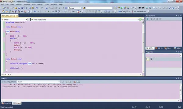
5. Write the program.
The code is shown below, copy it and paste it into the C file that is open in Atmel Studio. Save the file.
#include <avr/io.h>

void Delay(void);

int main(void)
{
    DDRB |= 1 << PB0;
    while(1)
    {
        PORTB &= ~(1 << PB0);
        Delay();
        PORTB |= 1 << PB0;
        Delay();
    }
}

void Delay(void)
{
    volatile unsigned int del = 16000;

    while(del--);
}
6. Build the project by clicking Build → Build attiny2313_blink on the top menu bar.
If the program build succeeded, the program can be loaded to the AVR – described next.
Programming the Device
To begin programming our microcontroller, we need to:
Confirm that the AVRISP mkII programmer is correctly connected to our computer via its USB interface.
In Atmel Studio, open the Device Programming dialog box by selecting “Tools” then “Device Programming” from the top menu.
By verifying our hardware connection and accessing the programming options through the menu bar, we can now use Atmel Studio’s functionality to deploy code to the physical ATtiny2313 chip on the breadboard via the AVRISP mkII programmer.
Let’s proceed to the next steps in the IDE to send our first “Blink” program to the microcontroller hardware.
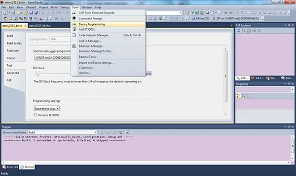
- With the Device Programming dialog box open, confirm the following settings:
- The Programming Tool should be set to “AVRISP mkII” to match our hardware programmer.
- Under Device, ensure “ATtiny2313” is accurately selected to correspond to the microcontroller in our circuit.
Once verified, click the “Apply” button to inform the IDE that we want to program an ATtiny2313 chip using the connected AVRISP mkII programmer.
By validating the settings are optimized for our circuitry, we prepare Atmel Studio to communicate properly with the chips on our breadboard via the USB programming device.
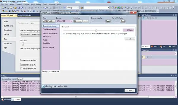
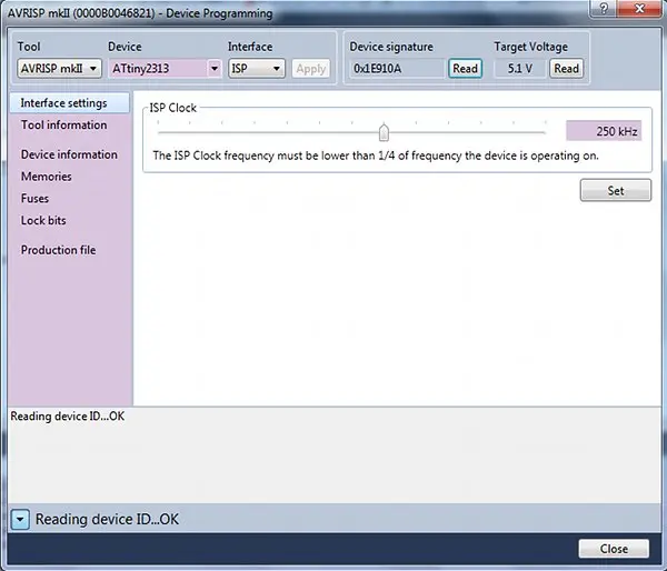
4. Test that the programmer can connect to the target.
With our circuit powered from the 5V supply, the next steps in the Device Programming dialog are:
- Click the “Read” button under “Target Voltage” to verify communication and read the voltage applied to our ATtiny2313 target chip.
- Then click “Read” under “Device Signature” to read and display the unique identification signature of the ATtiny2313 on the breadboard.
By taking these actions in the Device Programming window, Atmel Studio will attempt to detect the target microcontroller connected via the AVRISP mkII.
We should see appropriate voltage and signature values displayed if the IDE is successfully interfaced with our physical circuit. This confirms everything is setup correctly before we program code.
5. Program the device.
Now it’s time to program our first code onto the ATtiny2313 chip:
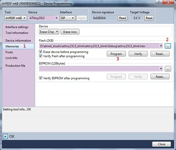
- In the Device Programming window, select “Memories” in the left pane.
- Under the “Flash” section, open the pre-compiled HEX file by clicking the browse [“…”] button.
- Navigate to the “Debug” folder of our project to select the “attiny2313_blink.hex” file.
- With the HEX file loaded, click the “Program” button to transfer the blinking LED code from the PC to the physical ATtiny2313 microcontroller on the breadboard.
By following these steps, we can use the Device Programming interface to deploy our compiled program onto the target hardware via the AVRISP mkII programmer.
To verify that the programming was successful, observe the behavior of the LED connected to our circuit. If all went well, the LED should now be:
Cycling between an illuminated ‘on’ state and an unilluminated ‘off’ state.
Flashing repeatedly as controlled by the code we loaded into the ATtiny2313 microcontroller.
Seeing the LED flash on and off indicates that our “Blink” program successfully transferred from the PC to the chip. The microcontroller is now executing the code and toggling the pin connected to the LED.
This confirms our setup and use of the AVRISP mkII programmer to load real programs onto the physical hardware circuit built around the ATtiny2313.
- What tools are required for AVR development in this tutorial?
The tutorial uses Atmel/Microchip Studio IDE on Windows and an AVRISP mkII USB programmer for AVR development. - Can I use an AVRISP mkII equivalent programmer?
Yes, equivalent USB programmers compatible with the AVRISP mkII standard will suffice. - What microcontroller is used for the blink project?
The ATtiny2313 microcontroller in DIP package (ATtiny2313-20PU) is used. - How is the circuit powered?
The circuit is powered by a 5V power supply. - How do I create the project in Atmel Studio?
Create a New Project, name it attiny2313_blink, and select Device Family tinyAVR and device ATtiny2313. - What code toggles the LED?
The provided C program configures PB0 as output and repeatedly clears and sets PORTB bit PB0 with a Delay function to blink the LED. - How do I verify the programmer is connected to the target?
Use Device Programming, click Read under Target Voltage and Read under Device Signature to verify communication and values. - How do I program the compiled HEX to the ATtiny2313?
In Device Programming select Memories, browse to the attiny2313_blink.hex in the Debug folder, then click Program. - How do I know programming succeeded?
Observe the LED cycling on and off; flashing indicates successful programming and execution.