1. Introduction
For our final project we built an ATmega32 based stepper motor controller which measures the angular position of the motor shaft using an optical encoder and quadrature decoder. Our system performs 3 basic functions:
(1) Communicate with a PC by means of a RS-485 interface, and
(2) Generates step and direction signals for a US digital MD1 microstep drive, and
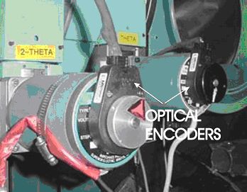
(3) Monitors the stepper motor rotor shaft by means of an optical encoder.

Shown above is a basic block diagram of our system with the circled numbers corresponding to the 3 basic functions above. We built block B, the ATmega32 controller.
2. High Level Design
In scientific laboratories stepper motors are used to mechanically position just about everything: monochrometers, diffractometers, translation stages, slits, optical tables, etc. Historically, stepper motors have been used because they stand up well to radiation, can in many instances be used open loop, are relatively simple to interface, and are cheap. Unfortunately, for critical applications, any slippage of the motor shaft ends up corrupting data, hence our interest in knowing the angular position of the motor shaft.
The picture on the left above is of two stepper motors with optical encoders on a four circle diffractometer. On the right is a hand drawn dial indicator which uses a paper clip as a reference marker; in the lower right hand corner are two stepper motors.
Scientific labs use two motor coordinate systems called user and dial coordinates. These coordinates are physical units, either millimeters or degrees of arc. The scientist places his sample in the beam, a laser beam or x-ray beam, and defines this as the zero position in user coordinates. At the zero position is user coordinates the scientist next enters the dial indicator reading on his apparatus into the software. It is important to note that sense (the direction) of the dial coordinates can be opposite the sense of user coordinates, but in all cases both coordinate systems are in the same physical units. The scientist then defines the scan or data gathering direction as positive while the rewind direction is negative. Backlash is used in the rewind direction to minimize errors in any gearing.
Stepper motors in scientific labs usually use a ‘tweak’ or jog motion function as well as incremental and absolute motion functions in user coordinates. Also, stepper motors usually have software and hardware limits which are supported in both coordinate systems.
Our high level design was to mimic as closely as possible how stepper motors are normally used in a scientific lab but rather than operate open loop, to also install an optical encoder on a double shafted stepper motor and use the optical encoder signals as feedback to our controller. To decode the optical encoder we used an LS7266R1 dual 24-bit quadrature counter to decode and count the encoder signals from the optical encoder.
3. Design Specification
We take the basic definitions of user and dial coordinates as well as the definitions of motion and rates of motion which follow, as the specification for our controller system. From this basic specification, a communications protocol is then established, as well as the basic control language used to control our ATmega32 motor controller. The hardware interfaces which we have implement naturally fall out of the specification which follows.
The two basic stepper motor velocity profiles for scan (forward or positive movement) and reverse (rewind or negative movement) are first defined. The basic equations of motion are given and then user and dial units are rationalized as they relate to our controller.
We used a US Digital MD1 10 MicroStep controller in our design for finer angular resolution of the motor shaft. Most stepper motors have 200 steps per revolution. With a microstepper there are 2000 microsteps per revolution. The optical encoder has 2000 lines per revolution. With a 4 times decode this yields 8000 counts per revolution; a well matched resolution for the MD1 microstepper.
3.1 Definition of Rates and Units
3.1.1 Base rate
Base rate is also called start rate, velocity base, base frequency or start frequency. Usually the base rate has units of Hertz but it is useful to think in units of steps per second. By abuse of language, steps per second is really microsteps per second and a step pulse is a microstep pulse.
The base rate is the rate from which a stepper motor can reliably start from rest. Similarly for a motor moving at its base rate, once step pulses to the motor stop, the motor reliably come to rest at its last position, i.e., last step.
Said another way, a stopped stepper motor can be instantaneously accelerated to its base rate and instantaneously decelerated from its base rate to a stopped position. Implied in the above is that a stepper motor at base rate Vb can be instantaneously decelerated to a stopped position and then instantaneously accelerated to Vb. For a stepper motor a typical base rate is 500 Hertz (microsteps per second).
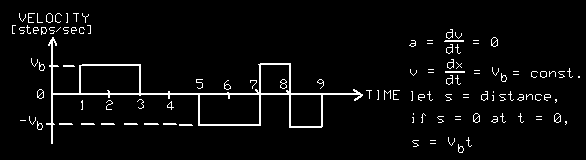
he drawing above shows a stepper motor stepped at its base rate. If Vb is clockwise (cw) then the motor is stepped cw at t1 and t2, then counterclockwise (ccw) at t5 and t6, then cw at t7 and finally ccw at t8; after the foregoing movement the motor should be in exactly to same position as when it started.
3.1.2 Steps per degree/mm
The user is interested in the final movements of the stepper motor, such as one millimeter or one degree. As such there is a conversion factor defined for a given motor which relates steps, or in our case microsteps to the user units of degrees or millimeters. If you take the output shaft of a stepper motor as the movement you are interested in: the stepper motor has 200 steps/rev. and the MD1 Microstep Drive has 10 microsteps/step for 2000 microsteps per revolution. Given 360 degrees per revolution the conversion factor is 50/9 microsteps per degree or inversely 18/100 degrees per microstep; so each microstep is = 0.18 degrees of arc movement. The foregoing is for the output shaft of the stepper motor. Accordingly, if you affix a 10:1 gear reducer on the stepper motor then the output shaft will move 0.018 degrees of arc per microstep.
3.1.3 Acceleration time
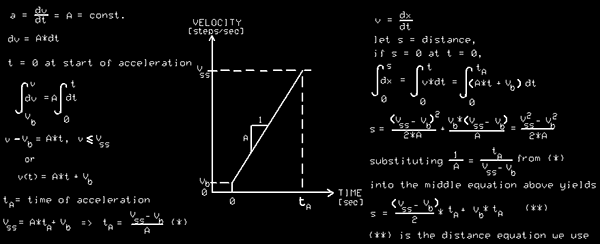
Our motor controller uses a constant acceleration or linear velocity ramp to accelerate to its steady state velocity, Vss, followed by a period of constant velocity and ending with a similar period of constant deceleration to a stop. The time of acceleration is made equal to the time of deceleration.
The drawing below shows the acceleration velocity profile of a stepper motor going from its base rate, Vb, to its steady state rate, Vss, over an acceleration time of tA. The basic equations of motion for acceleration are also given.
A reasonable set of units would be steady state rate Vss = 5000 Hz, base rate Vb = 500 Hz., and acceleration time tA = .25 seconds. With a conversion rate of 2000 steps / revolution (2*phi), this gives an acceleration of 18*phi radians/ sec2.
3.1.4 Forward movement
Shown below is the velocity profile of a complete forward movement of a stepper motor. By convention for scientific instruments forward movement is positive movement and is the direction in which data are gathered. Forward movement is the scan direction.
Parts list:
# |
Part Name |
Description |
Price |
| 1 | C1 | 0.1 uf |
0.14 |
| 2 | C2 | 0.1 uf |
0.14 |
| 3 | C3 | .47 uf |
0.28 |
| 4 | C4 | 0.1 uf |
0.14 |
| 5 | C5 | 0.1 uf |
0.14 |
| 6 | C6 | 0.1uf |
0.14 |
| 7 | C7 | 0.1 uf |
0.14 |
| 8 | C8 | 470 uf,100V |
0.60 |
| 9 | C9 | 0.1 uf |
0.14 |
| 10 | C10 | 0.1 uf |
0.14 |
| 11 | C11 | 0.1 uf |
0.14 |
| 12 | C12 | 10 uf,15V |
0.35 |
| 13 | C13 | 10 uf,15V |
0.35 |
| 14 | C14 | 22pf |
0.25 |
| 15 | C15 | 22pf |
0.25 |
| 16 | C16 | .47uf |
0.35 |
| 17 | C17 | .47uf |
0.35 |
| 18 | C18 | .47uf |
0.35 |
| 19 | C19 | 47 nf |
0.35 |
| 20 | C20 | 0.1 uf |
0.14 |
| 21 | D1 | SM6T6V8CA |
0.17 |
| 22 | H1 | JTAG |
0.35 |
| 23 | H2 | HEADER 2 x 5 |
0.35 |
| 24 | H5 | HEADER 2 x 5 |
0.35 |
| 25 | L1 | VK-20010-3S4 |
0.45 |
| 26 | L3 | VK-20010-3S4 |
0.45 |
| 27 | R1 | 120 |
0.07 |
| 28 | R2 | 100 |
0.02 |
| 29 | R3 | 10K |
0.04 |
| 30 | R4 | 1K |
0.02 |
| 31 | R5 | 1K |
0.02 |
| 32 | R6 | 680 |
0.05 |
| 33 | R7 | 120K |
0.07 |
| 34 | R30 | 1K |
0.02 |
| 35 | RN1 | 220 |
0.25 |
| 36 | S1 | SWITCH (NO) |
2.25 |
| 37 | SPROG3 | HEADER 2 x 3 |
0.21 |
| 38 | U1 | AM26C32 |
0.80 |
| 39 | U2 | 74HC153 |
0.63 |
| 40 | U4 | LS7266R1 |
11.25 |
| 41 | U5 | MAX487 |
2.81 |
| 42 | U6 | ILD31 |
1.00 |
| 43 | U7 | 74LS04 |
0.35 |
| 44 | U10 | 74LS74 |
0.38 |
| 45 | U11 | 74LS01 |
0.25 |
| 46 | U704 | ATmega32 |
5.20 |
| 47 | J1 | DB-9 |
2.14 |
| 48 | H1 | Term.Block |
1.11 |
| 49 | J2 | Phone jack x2 |
1.16 |
TOTAL |
37.10 |
For more detail: Stepper Motor Indexer & Decoder ECE 476: Spring 2005