Project Introduction
Temperature is an important indicator of the environment and is used as a control parameter in many projects. The temperature alarm can be used for smart home appliances or environmental indicators of temperature measurement, can be used for practical electronic temperature alarm, such as the measurement of computer case temperature, but also for industrial temperature measurement and control
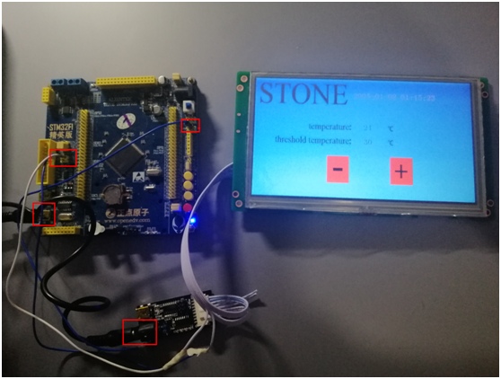
STM32ZET6 system board as the MCU’s main control board, 5V power supply; the control circuit controls the DS18B20 circuit to achieve temperature detection, control the alarm circuit to achieve the alarm; and STONE HMI display module through the serial port UART1 to achieve communication; STVC070WT-01 power supply is a 12V power supply module.
Hardware introduction.
- CPU selection is ST’s STM32F103ZET6
- The display is STONE STVC070WT-01 programmable display
- The temperature detector model is DS18B20
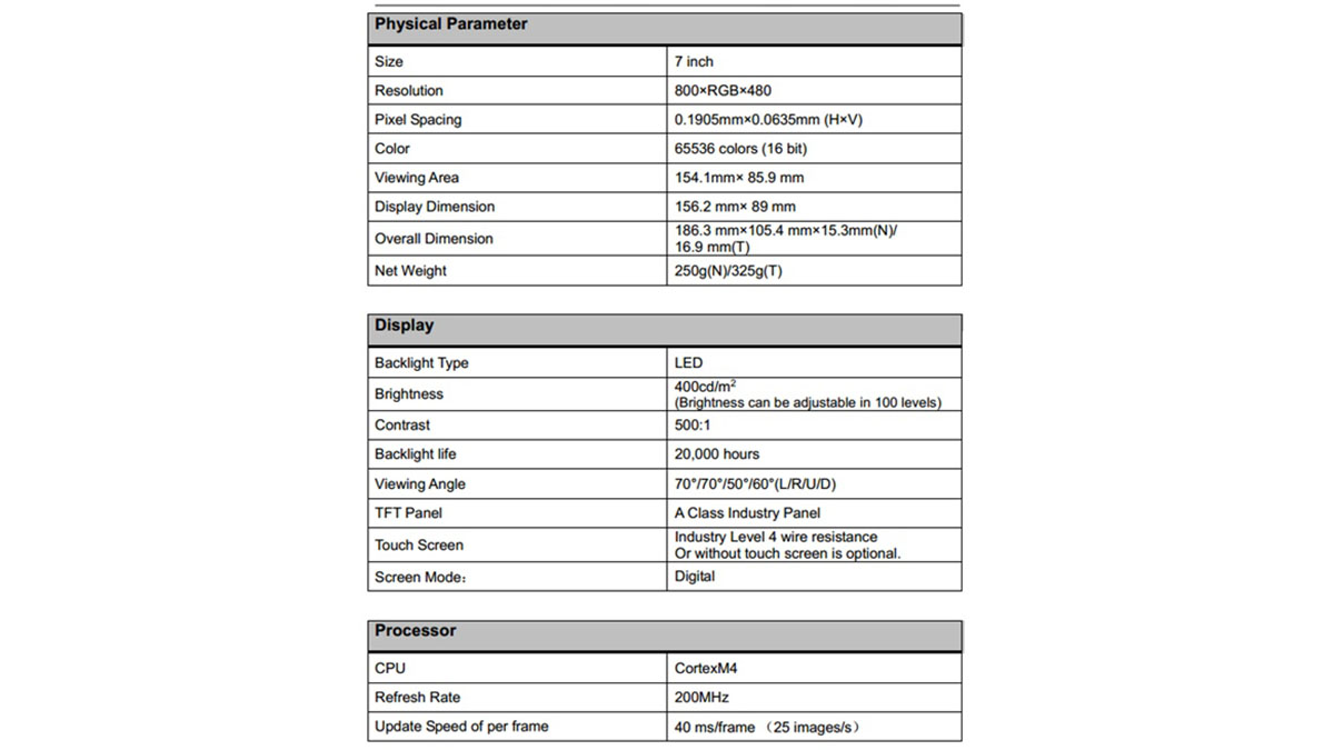
The controller uses STONE display module is STVC070WT-01, 7 inch resolution is 800*480, the processor is CortexM4, refresh rate is 200MHZ, the frame rate of the screen is 40ms/frame (i.e. 25 images/second), flash memory 128M (can be externalized 1GB). The screen weight is 325 g. Detailed parameters are shown in the following table.
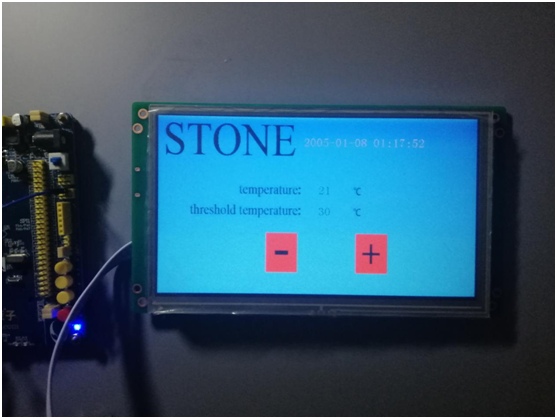
Screen images:

Main functions covered
STVC070WT-01 is TFT display and touch controller. It includes processor, control program, driver, flash memory, RS232/RS485/TTL port, touch screen, power supply, etc. It is a powerful display system with simple operating system and can be controlled by any microcontroller. STVC070WT-01 can be used to perform all basic functions such as text display, image display, curve display, touch function, video and audio function, etc.
-Built-in Cortex CPU and driver
-Can be controlled by any microcontroller
-Display picture/text/curve
– 65536 color TFT display
-Can be operated by touch
– RS232/ RS485/ TTL UART interface and USB port
-Wide voltage range
Introduction to the general design of the system
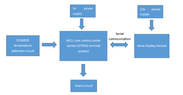
As shown above, the overall design of the system, STM32ZET6 system board as the main control board of MCU, 5V power supply; this control circuit control DS18B20 circuit to achieve temperature detection, control alarm circuit to achieve alarm; and STONE display module through the serial port UART1 to achieve communication; STVC070WT-01 power supply is a 12V power supply module.
Hardware Description
MCU——STM32F103ZET6
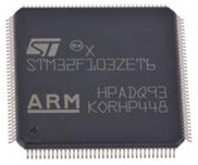
As shown in the figure, the CPU of this design is ST’s STM32F103ZET6, which is a 32-bit microcontroller chip with ARM CORTEXM3 core in 144-LQFP package, STM32F103 series microprocessor with 72 MHz CPU speed and up to 1 MB of flash memory (SRAM 96 Kb). Motor control peripherals and full-speed CAN and USB interfaces are included. Operates at low power, low voltage, and combines excellent performance with real-time functionality. A family of package types is available for embedded applications.
The MCU architecture features an easy-to-use STM32 platform for applications including motor drives; PC and gaming; HVAC and industrial applications. The STM32 family benefits from Cortex-M3 architecture enhancements, including Thumb-2 instructions set to convey improved performance with better coding density and faster response to interrupts, all in line with leading industrial power consumption. all aligned with leading industrial power consumption. It offers excellent real-time performance, superior efficacy, cross-family pinout, high peripheral and software compatibility, high integration, and a market price of around $20.
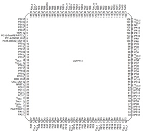
Figure 1 below is the STM32F103ZET6 chip physical diagram, and Figure 2 is the STM32F103ZET6 chip pin diagram. there are five main categories of STM32F103ZET6 pins, the first category is non-GPIO single function pins, such as power pins and reset pins; the second category is GPIO single function pins, only ordinary input and output functions; the third category is the main function multiplexed The fourth category is the multi-functional GPIO pins whose main function is GPIO, for example, PC0 is used as a normal input and output IO port and as an ADC pin; the fifth category is the GPIO pins whose main function is mapping function, which has the function of function mapping and can map other function pins to this pin, for example CAN1_RX can be mapped to PB8.
Temperature detector: DS18B20
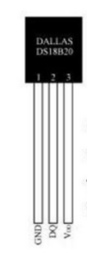
DS18B20 is a temperature sensor, here is used to measure the temperature of water, DS18B20 output is a digital signal is generally used for microcontrollers to read its data, and through certain processing to get the temperature data, generally with a single bus protocol to communicate (in fact, strictly speaking DS18B20 belongs to a temperature detection chip, because it is not a sensor in the sense of the (In fact, strictly speaking, DS18B20 belongs to a temperature detection chip, because it is not a sensor in the sense of something else, but there are other integrated circuits inside, so it can read data with microcontrollers and so on as long as it conforms to its communication).
Its wiring diagram is shown in the second picture below, the DS18B820 flat side as the front, the chip pins from do to the right in the order of the chip’s GND, data port, VCC, in the use of the middle of the data port is generally connected to the microcontroller, that is, with a single bus protocol for communication and read data. than this temperature, otherwise it will burn the chip.
Software Description
MCU Programming
The MCU program is elaborated in two parts, one is the alarm logic part and one is the temperature threshold setting part. Of course, the process of serial port is also included in it
1、Alarm program
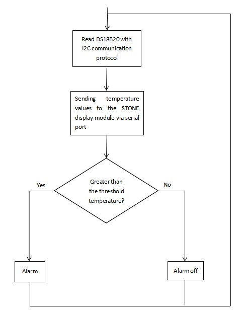
As shown in the flow chart of the alarm program, firstly, the MCU will communicate with the DS18B20 digital temperature sensor through the I2C protocol to obtain the data value generated by the sensor with the change of temperature; then the MCU will convert this data value into temperature and transmit the temperature value to the receiving pin of the STONE display module through the transmit port of the serial port. If the result is yes, the alarm command will be executed to drive the alarm circuit to realize the alarm; if the result is no, the alarm command will be executed to drive the alarm circuit to realize the alarm off.
2、Temperature threshold setting procedure
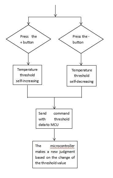
As shown in the figure is the flow chart of the alarm program, the temperature threshold setting is done on the screen, first of all, the touch screen of the screen to determine whether to press the “+” “-” key, if the “+” key is pressed then If the “+” key is pressed, the temperature threshold value increases, and if the “-” key is pressed, the temperature threshold value decreases; the judgment result is otherwise pressed all the time, the screen will always scan to detect the two keys.
If a key is pressed and the data is updated, the screen will send the threshold data to the MCU in accordance with the instructions in the format corresponding to the screen, and the MCU will make processing or temperature threshold data according to the instructions, and change the value of the threshold cache variable of the microcontroller according to the change of the threshold value, so as to make a new judgment to achieve real-time alarm function.
TOOL 2019 UI Design
1、General layout design of the interface
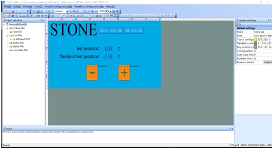
The following figure shows the layout and file arrangement of the screen UI design for the STONE test project.
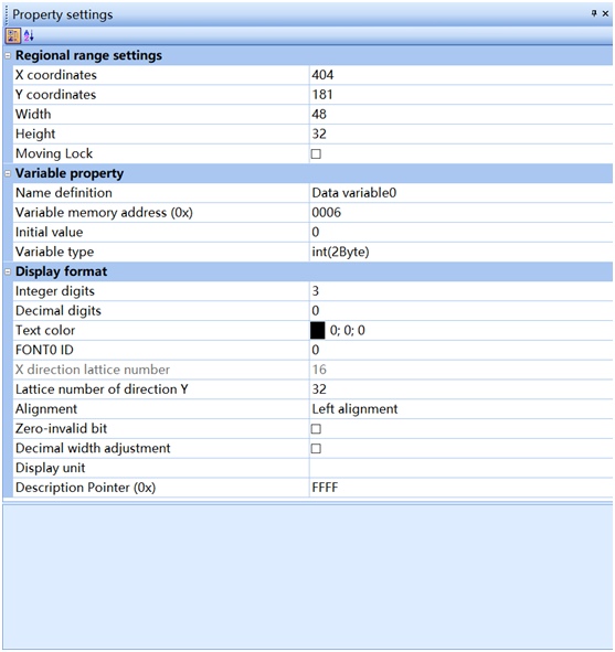
2、The design of the text box
The text box settings mainly set the parameter storage address and parameter type, as well as the initial value and the number of bits to be displayed. The display of the text box number is associated with the address and shows the data value of the address in the screen module.
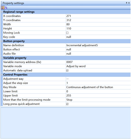
The design of the button is the same as that of the text box, but note that the Adjustment way should be filled in to adjust the way the interaction works.
Wiring
1、Wiring of power supply
The screen is powered by the rated voltage, connect 12V, use the external 12V power adapter to connect to the power terminal of the STONE power board, the MCU control board is powered by 5V, use the corresponding data cable of USB-mini to connect correctly. At the same time, it is necessary to make the two power supplies common ground, that is, the MCU control board and STONE display module should have a GND connection with each other.
2, the data port serial data line connection
Serial communication data lines to be connected to two, the screen’s transmitter to connect to the MCU’s receiver, the screen’s receiver to connect to the MCU’s transmitter, respectively, the screen’s DIN to connect to the microcontroller’s PA9, the screen’s DOUT to connect to the microcontroller’s PA10.
Application of the project
Temperature is an important indicator of the environment and is also used as a control parameter in many projects. The temperature alarm can be used for smart home appliances or environmental indicators of temperature measurement, can be used for practical electronic temperature alarm, such as computer case temperature measurement, but also for industrial temperature measurement and control, if you want to measure the temperature of the liquid can buy the DS18B20 plastic package of the device.
Appendix: STM32 driver code
/*uart.c*/
#include “sys.h”
#include “usart.h”
//////////////////////////////////////////////////////////////////////////////////
//If you are using ucos, just include the following header file.
#if SYSTEM_SUPPORT_OS
#include “includes.h” //ucos Usage
#endif
//Add the following code to support the printf function without having to select use MicroLIB
#if 1
#pragma import(__use_no_semihosting)
//Support functions needed for the standard library
struct __FILE
{
int handle;
};
FILE __stdout;
//Define _sys_exit() to avoid using semi-host mode
void _sys_exit(int x)
{
x = x;
}
//Redefine the fputc function
int fputc(int ch, FILE *f)
{
while((USART1->SR&0X40)==0);//Send in a loop until it is finished
USART1->DR = (u8) ch;
return ch;
}
#endif
/*Methods of using microLib*/
/*
int fputc(int ch, FILE *f)
{
USART_SendData(USART1, (uint8_t) ch);
while (USART_GetFlagStatus(USART1, USART_FLAG_TC) == RESET) {}
return ch;
}
int GetKey (void) {
while (!(USART1->SR & USART_FLAG_RXNE));
return ((int)(USART1->DR & 0x1FF));
}
*/
#if EN_USART1_RX //If it is enabled, receive
//Serial port 1 interrupt service program
//Note that reading USARTx->SR can avoid inexplicable errors.
u8 USART_RX_BUF[USART_REC_LEN]; //Receive buffer, maximum USART_REC_LEN bytes.
//Receiving Status
//bit15, Receive completion flag
//bit14, Received 0x0d
//bit13~0, Number of valid bytes received
u16 USART_RX_STA=0; //Receive status marker
void uart_init(u32 bound){
GPIO_InitTypeDef GPIO_InitStructure;
USART_InitTypeDef USART_InitStructure;
NVIC_InitTypeDef NVIC_InitStructure;
RCC_APB2PeriphClockCmd(RCC_APB2Periph_USART1|RCC_APB2Periph_GPIOA, ENABLE); //Clock
//USART1_TX GPIOA.9
GPIO_InitStructure.GPIO_Pin = GPIO_Pin_9; //PA.9
GPIO_InitStructure.GPIO_Speed = GPIO_Speed_50MHz;
GPIO_InitStructure.GPIO_Mode = GPIO_Mode_AF_PP;
GPIO_Init(GPIOA, &GPIO_InitStructure);//GPIOA.9
//USART1_RX GPIOA.10
GPIO_InitStructure.GPIO_Pin = GPIO_Pin_10;//PA10
GPIO_InitStructure.GPIO_Mode = GPIO_Mode_IN_FLOATING;
GPIO_Init(GPIOA, &GPIO_InitStructure);//GPIOA.10
//Usart1 NVIC
NVIC_InitStructure.NVIC_IRQChannel = USART1_IRQn;
NVIC_InitStructure.NVIC_IRQChannelPreemptionPriority=3 ;
NVIC_InitStructure.NVIC_IRQChannelSubPriority = 3;
NVIC_InitStructure.NVIC_IRQChannelCmd = ENABLE;
NVIC_Init(&NVIC_InitStructure);
//USART
USART_InitStructure.USART_BaudRate = bound;
USART_InitStructure.USART_WordLength = USART_WordLength_8b;
USART_InitStructure.USART_StopBits = USART_StopBits_1;
USART_InitStructure.USART_Parity = USART_Parity_No;
USART_InitStructure.USART_HardwareFlowControl = USART_HardwareFlowControl_None;
USART_InitStructure.USART_Mode = USART_Mode_Rx | USART_Mode_Tx;
USART_Init(USART1, &USART_InitStructure);
USART_ITConfig(USART1, USART_IT_RXNE, ENABLE);
USART_Cmd(USART1, ENABLE);
}
u8 USART_RX_END=0;
void USART1_IRQHandler(void) //Uart1 handler
{
u8 Res;
if(USART_GetITStatus(USART1, USART_IT_RXNE) != RESET)
{
Res =USART_ReceiveData(USART1);
if(USART_RX_END==0)
{
USART_RX_BUF[USART_RX_STA]=Res ;
USART_RX_STA++;
if(USART_RX_STA>8)
{
USART_RX_END=1;
}
}
}
}
#endif
/*ds18b20.c*/
#include “ds18b20.h”
#include “delay.h”
//Reset DS18B20
void DS18B20_Rst(void)
{
DS18B20_IO_OUT(); //SET PG11 OUTPUT
DS18B20_DQ_OUT=0; //Pull down the DQ
delay_us(750); //Pull down the 750us
DS18B20_DQ_OUT=1; //DQ=1
delay_us(15); //15US
}
//Waiting for response from DS18B20
//Return 1: DS18B20 not detected
//Return 0:Exist
u8 DS18B20_Check(void)
{
u8 retry=0;
DS18B20_IO_IN(); //SET PG11 INPUT
while (DS18B20_DQ_IN&&retry<200)
{
retry++;
delay_us(1);
};
if(retry>=200)return 1;
else retry=0;
while (!DS18B20_DQ_IN&&retry<240)
{
retry++;
delay_us(1);
};
if(retry>=240)return 1;
return 0;
}
//Read a bit from the DS18B20
//Return value: 1/0
u8 DS18B20_Read_Bit(void)
{
u8 data;
DS18B20_IO_OUT(); //SET PG11 OUTPUT
DS18B20_DQ_OUT=0;
delay_us(2);
DS18B20_DQ_OUT=1;
DS18B20_IO_IN(); //SET PG11 INPUT
delay_us(12);
if(DS18B20_DQ_IN)data=1;
else data=0;
delay_us(50);
return data;
}
//Read a byte from DS18B20
//Return value: the read data
u8 DS18B20_Read_Byte(void)
{
u8 i,j,dat;
dat=0;
for (i=1;i<=8;i++)
{
j=DS18B20_Read_Bit();
dat=(j<<7)|(dat>>1);
}
return dat;
}
//Write a byte to the DS18B20
//dat: bytes to be written
void DS18B20_Write_Byte(u8 dat)
{
u8 j;
u8 testb;
DS18B20_IO_OUT(); //SET PG11 OUTPUT;
for (j=1;j<=8;j++)
{
testb=dat&0x01;
dat=dat>>1;
if (testb)
{
DS18B20_DQ_OUT=0; // Write 1
delay_us(2);
DS18B20_DQ_OUT=1;
delay_us(60);
}
else
{
DS18B20_DQ_OUT=0; // Write 0
delay_us(60);
DS18B20_DQ_OUT=1;
delay_us(2);
}
}
}
//Start temperature conversion
void DS18B20_Start(void)
{
DS18B20_Rst();
DS18B20_Check();
DS18B20_Write_Byte(0xcc); // skip rom
DS18B20_Write_Byte(0x44); // convert
}
//Initialize the DS18B20’s IO port DQ while detecting the presence of DS
//Return 1:Does not exist
//Return 0:Exist
u8 DS18B20_Init(void)
{
GPIO_InitTypeDef GPIO_InitStructure;
RCC_APB2PeriphClockCmd(RCC_APB2Periph_GPIOG, ENABLE); //Enables the PORTG port clock
GPIO_InitStructure.GPIO_Pin = GPIO_Pin_11; //PORTG.11 Push-Pull Output
GPIO_InitStructure.GPIO_Mode = GPIO_Mode_Out_PP;
GPIO_InitStructure.GPIO_Speed = GPIO_Speed_50MHz;
GPIO_Init(GPIOG, &GPIO_InitStructure);
GPIO_SetBits(GPIOG,GPIO_Pin_11); //Output 1
DS18B20_Rst();
return DS18B20_Check();
}
//Get temperature value from ds18b20
//Accuracy: 0.1C
//Return value: Temperature value (-550~1250)
short DS18B20_Get_Temp(void)
{
u8 temp;
u8 TL,TH;
short tem;
DS18B20_Start (); // ds1820 start convert
DS18B20_Rst();
DS18B20_Check();
DS18B20_Write_Byte(0xcc); // skip rom
DS18B20_Write_Byte(0xbe); // convert
TL=DS18B20_Read_Byte(); // LSB
TH=DS18B20_Read_Byte(); // MSB
if(TH>7)
{
TH=~TH;
TL=~TL;
temp=0; //Temperature is negative
}else temp=1; //Temperature is positive
tem=TH; //Obtaining the high octet
tem<<=8;
tem+=TL; //Obtaining the low octet
tem=(float)tem*0.625; //convert
if(temp)return tem; //return temperature value
else return -tem;
}
/*key.c*/
#include “stm32f10x.h”
#include “key.h”
#include “sys.h”
#include “delay.h”
//Key initialization function
void KEY_Init(void) //IO initialization
{
GPIO_InitTypeDef GPIO_InitStructure;
RCC_APB2PeriphClockCmd(RCC_APB2Periph_GPIOA|RCC_APB2Periph_GPIOE|RCC_APB2Periph_GPIOB,ENABLE);//Enable PORTA, PORTE clock
GPIO_InitStructure.GPIO_Pin = GPIO_Pin_2|GPIO_Pin_3|GPIO_Pin_4;//KEY0-KEY2
GPIO_InitStructure.GPIO_Mode = GPIO_Mode_IPU; //Set to pull-up input
GPIO_Init(GPIOE, &GPIO_InitStructure);//Initialize GPIOE2,3,4
//初始化 WK_UP–>GPIOA.0 Dropdown input
GPIO_InitStructure.GPIO_Pin = GPIO_Pin_0;
GPIO_InitStructure.GPIO_Mode = GPIO_Mode_IPD; //PA0 set to input, default drop-down
GPIO_Init(GPIOA, &GPIO_InitStructure);//Initialize GPIOA.0
GPIO_InitStructure.GPIO_Pin = GPIO_Pin_8; //BEEP–>PB.8 Port Configuration
GPIO_InitStructure.GPIO_Mode = GPIO_Mode_Out_PP; //Push-Pull output
GPIO_InitStructure.GPIO_Speed = GPIO_Speed_50MHz; //Speed is 50MHz
GPIO_Init(GPIOB, &GPIO_InitStructure); //Initialize GPIOB according to parameters.8
GPIO_ResetBits(GPIOB,GPIO_Pin_8);//output 0, turn off the buzzer output
}
//Key processing function
//return key value
//mode:0,do not support continuous pressing;1,support continuous pressing;
//0, no key pressed
//1, KEY0 is pressed
//2, KEY1 pressed
//3, KEY2 pressed
//4, KEY3 pressed WK_UP
//Note that this function has a response priority, KEY0>KEY1>KEY2>KEY3!u8 KEY_Scan(u8 mode)
{
static u8 key_up=1;//key press to release the flag
if(mode)key_up=1; //support continuous press
if(key_up&&(KEY0==0||KEY1==0||KEY2==0||WK_UP==1))
{
delay_ms(10);//de-jitter
key_up=0;
if(KEY0==0)return KEY0_PRES;
else if(KEY1==0)return KEY1_PRES;
else if(KEY2==0)return KEY2_PRES;
else if(WK_UP==1)return WKUP_PRES;
}else if(KEY0==1&&KEY1==1&&KEY2==1&&WK_UP==0)key_up=1;
return 0;// No button pressed
}
/*main.c*/
#include “stm32f10x.h”
#include “usart.h”
#include “delay.h”
#include “../BOARD/ws2812/ws2812.h”
#include “ds18b20.h”
#include “key.h”
int set_temp=40;
struct RGB_COLOR
{
u8 C_RED;
u8 C_GREEN;
u8 C_BLUE;
u8 C_WHITE;
u8 C_RED_FLAG;
u8 C_GREEN_FLAG;
u8 C_BLUE_FLAG;
};
#define ICON_WHITE_ADDR 0x02
#define ICON_RED_ADDR 0x03
#define ICON_GREEN_ADDR 0x04
#define ICON_BLUE_ADDR 0x05
#define TEXT_RED_ADDR 0x07
#define TEXT_GREEN_ADDR 0x08
#define TEXT_BLUE_ADDR 0x09
#define TEXT_WHITE_ADDR 0x06
#define SWITCH_ONOFF_ADDR 0x01
#define ICON_ON 0x01
#define ICON_OFF 0x00
u8 data_send[8]= {0xA5, 0x5A, 0x05, 0x82, 0x00, 0x09, 0x00,0x02};
//u8 data_ico[24] = {0xA5, 0x5A, 0x14, 0x85, 0x00, 0x09, 0x00 ,0x02 ,0x00 ,0x00 ,0xff ,0xff ,0xff,0xff,0xff,0xff,0xff,0xff,0xff,0xff,0xff,0xff, 0xff,0xff};
void UART1_Send_Array(u8 send_array[],unsigned char num)
{
u8 i=0;
while(i<num)
{
USART_SendData(USART1,send_array[i]);
while( USART_GetFlagStatus(USART1,USART_FLAG_TC)!= SET);
i++;
}
}
int main(void)
{
u8 t=0;
// vu8 key=0;
short temperature;
u8 temprature=20;
KEY_Init();
NVIC_PriorityGroupConfig(NVIC_PriorityGroup_2);//Set interrupt priority grouping to group 2: 2 bits preemption priority, 2 bits response priority
uart_init(115200);
delay_init();
struct RGB_COLOR USER_RGB_COLOR;
USER_RGB_COLOR.C_BLUE=0;
USER_RGB_COLOR.C_GREEN=0;
USER_RGB_COLOR.C_RED=0;
USER_RGB_COLOR.C_RED_FLAG=1;
USER_RGB_COLOR.C_GREEN_FLAG=1;
USER_RGB_COLOR.C_BLUE_FLAG=1;
u16 k,q;
u8 BLINK_2=0;
u8 USER_R=0,USER_G=0,USER_B=0,COLOR_TYPE=0,COLOR_DIR=0;
u8 blink_type=0;
u16 times=0;
RGB_LED_Init();
DS18B20_Init();
// ws281x_colorWipe(ws281x_color(0, 0, 0), 10);
// RGB_LED_Write_24Bits(USER_RGB_COLOR.C_RED, USER_RGB_COLOR.C_GREEN, USER_RGB_COLOR.C_BLUE);
while(1)
{
// delay_ms(1000);
temperature=DS18B20_Get_Temp();
data_send[5]=0x06;
data_send[6]=0x00;
data_send[7]=(temperature/10);
UART1_Send_Array(data_send,8);
if(USART_RX_END)
{
switch (USART_RX_BUF[5])
{
case RED_COLOR:
set_temp=USART_RX_BUF[8];
break;
default:
USART_RX_END=0;
USART_RX_STA=0;
break;
}
USART_RX_END=0;
USART_RX_STA=0;
}
if(temperature/10>=set_temp){GPIO_SetBits(GPIOB,GPIO_Pin_8); }
else {GPIO_ResetBits(GPIOB,GPIO_Pin_8); }
}
}
STONE display module control temperature alarm operation demonstration