Electrifying Engagement: Building a Quiz Buzzer Circuit for Interactive Quizzes
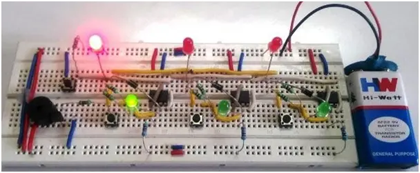
Circuit Diagram In the circuit diagram of the School/College quiz Buzzer circuit using the 555 IC, three 555 timer ICs are arranged in a bistable configuration. Each 555 IC has its own stable state controlled by individual buttons accessible to the participants. Additionally, there is a single button that manages the common stable state of […]
Electrifying Engagement: Building a Quiz Buzzer Circuit for Interactive Quizzes Read More »