Summary of Electrifying Engagement: Building a Quiz Buzzer Circuit for Interactive Quizzes
This article describes a school quiz buzzer circuit using three 555 timer ICs in a bistable configuration. The system allows three participants to press individual buttons (P1, P2, P3), with the first press triggering an output that illuminates a green LED and sounds a buzzer while disabling other inputs until a reset button is pressed.
Parts used in the School/College Quiz Buzzer Circuit:
- Three 555 Timer ICs
- Participant Buttons (P1, P2, P3)
- Reset Button (ORG)
- Green LEDs
- Red LED
- Buzzer
- NPN Transistor BC547
- Diodes
- 9V Battery
- Resistors
Circuit Diagram
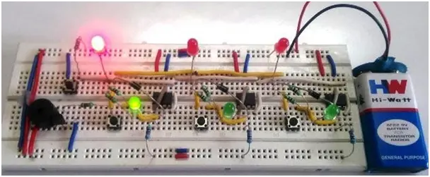
In the circuit diagram of the School/College quiz Buzzer circuit using the 555 IC, three 555 timer ICs are arranged in a bistable configuration. Each 555 IC has its own stable state controlled by individual buttons accessible to the participants. Additionally, there is a single button that manages the common stable state of all the timer ICs, allowing the organizer to reset the entire circuit. Pressing any of the buttons, P1, P2, or P3, causes the corresponding TRIGGER pin to go low, leading the timer to shift its stable state. Consequently, the output pin of the relevant timer goes high, illuminating the green LED associated with the participant and initiating the buzzer sound.
The functionality involves disabling the other timers once the first stable state of any timer is set. This occurs because the forward-biased diode connected to the output pin of the set timers becomes forward-biased, causing the remaining button terminals to go high. Consequently, even if other buttons are pressed subsequently, the corresponding timer’s pin only receives a high signal. As a result, the buttons only operate after resetting the entire circuit. The buzzer is regulated by an NPN transistor BC547, with its control signal being the common TRIGGER to which the buttons are linked. Additionally, the buttons are grounded through the internal diode of the transistor.
Working of Quiz Buzzer Circuit:
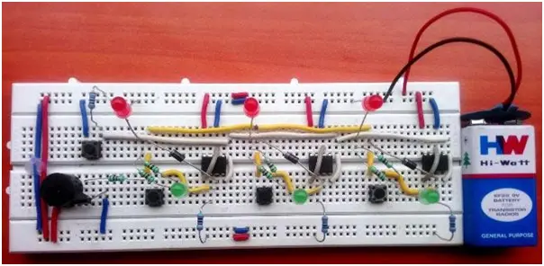
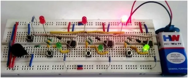
The entire circuit is powered by a 9V battery. Initially, the circuit is in a RESET condition, awaiting a TRIGGER signal. Upon the participant pressing the button, the respective timer undergoes a state change, causing the output to go high and the buzzer to sound, signifying the button press. The image below illustrates that button P1 is pressed, disabling the remaining buttons.
Upon pressing the RESET button (ORG), the circuit returns to its initial state, ready to await the next TRIGGER.
The GREEN LED signals the participant that they have pressed the button first. Simultaneously, the RED LED notifies the organizer about the initial button press. Upon the third participant pressing the button, the associated LED will illuminate, triggering the sounding of the buzzer.
This sequence can be repeated as many times as desired. If the inclusion of a buzzer in the circuit is unnecessary, both the BC547 transistor and the buzzer can be removed. However, the resistor linked to the base of the transistor should be directly connected to the ground. Alternatively, if there is a preference to incorporate a buzzer on each participant’s side, it can be added using an NPN transistor on PIN 3 of each 555 timer.
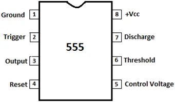
PIN DIAGRAM OF 555 TIMER IC:
- How does the circuit prevent multiple participants from winning simultaneously?
Once one timer sets its stable state, its forward-biased diode causes remaining button terminals to go high, preventing subsequent presses from activating other timers. - What happens when a participant presses their button?
The corresponding TRIGGER pin goes low, shifting the timer's state, which makes the output pin go high to light the green LED and sound the buzzer. - How is the circuit reset for the next round?
Pressing the common RESET button (ORG) returns all timer ICs to their initial stable state, ready to await the next trigger. - Which component controls the buzzer sound?
An NPN transistor BC547 regulates the buzzer, receiving its control signal from the common TRIGGER line linked to the buttons. - Can the circuit function without a buzzer?
Yes; if a buzzer is unnecessary, the BC547 transistor and buzzer can be removed, and the resistor at the base of the transistor should be connected directly to ground. - How can you add a buzzer for each participant individually?
A buzzer can be added on each participant's side by connecting an NPN transistor to PIN 3 of each respective 555 timer. - What power source is required for this circuit?
The entire circuit is powered by a 9V battery. - What do the green and red LEDs indicate?
The green LED signals the specific participant who pressed the button first, while the red LED notifies the organizer about the initial press.