Summary of Teaching an old clock Using Atmega32
This project retrofits a vintage GE alarm clock with modern features like snooze, daily alarms, and AM/PM indication using an Atmega32 microcontroller. The system utilizes utility power for time synchronization, stepper motors to adjust the alarm wheel, and a solenoid to prevent unintended alarms. An LCD displays settings, while buttons allow user control. This upgrade preserves the clock's retro aesthetic while adding functionality previously missing due to its mechanical limitations.
Parts used in the Retro Alarm Clock Upgrade:
- Alarm Clock
- Solenoid
- Buttons
- Snooze Button
- LCD
- Stepper Motor
- Solder Board
- 5VDC Supply
- 9VDC Supply
- 9VAC Transformer
- PC Board
- Mega32 Microcontroller
- Jumper Cables
- Mega32 Socket
- Headers
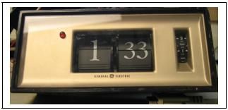
While exuding retro style, the alarm clock in its original state lacked many desirable features of today’s alarm clocks. The only controls consisted of a single on/off switch. It also lacked AM/PM indication, making it impossible to sleep for more than 12 hours.
Our project sought to maintain the integrity of the original alarm clock, while using a microcontroller to automatically manipulate the controls, in order to implement features like snooze, alarm reset, and daily alarms.
High Level Design
Motivation
The clock was purchased several years prior from Goodwill. Initially, the retro styling, and the annoyingly effective nature of the buzzer mechanism made it a favorite. However, the shortcomings quickly came to light under a typical highly variable college sleep schedule. Every night required preparation by manually turning the unidirectional alarm wheel and resetting the alarm to the on position. Once the alarm started to sound, there was no snooze mechanism or alarm reset to stop the alarm. Additionally, when it was time to make up for lost sleep, the nature of the clock mechanism allowed for a maximum of 12 hours of sleep. Eventually, the alarm functions of a cell phone replaced it as the preferred alarm clock.
Today, we are seeing a resurgence of retro style. In fact, “flip style” alarm clocks can be purchased new from various retailers. However, by reusing the old clock we can promote recycling, maintain the high build quality, and also make for a great project. At the same time, we were able to incorporate daily alarm features normally found only on more high end modern alarm clocks.
Logical Structure
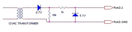
- Time Signal
- A circuit was constructed to convert the 60Hz 120VAC utility power into a 60Hz 5V digital signal, which we used to keep microcontroller time synchronized with that of the alarm clock
- PM Indication
- We mounted an LED to the front of the alarm clock to given a quick and easy indication of PM time
- Alarm Wheel Control
- The alarm works on a wheel type mechanism that activates the buzzer based on its position. This alarm wheel in the original clock is adjusted manually, but we added a stepper motor that gave us the ability to manipulate the alarm with MCU software
- Deactivating Alarms
- We maintained the full alarm mechanism of the original clock, which meant that an undesired alarm could potentially sound while manipulating the alarm wheel, as well as during the opposite AM/PM half of the day. To rectify this we added a solenoid which is able to temporarily deactivate the internal alarm mechanism
- User Controls
- The original controls consisted of only alarm and time setting gears, and a single on/off switch. In order to implement the desired functionality we added a total of 7 buttons for various functions
- User Interface
- We mounted a small LCD to the rear of the clock to enable to user to set and query alarms and settings
Tradeoffs
Certain desirable features have been left out of this project. For instance, we had the idea of automatically adjusting the alarm clock time to adjust for daylight savings, etc. However, this would have required more extensive hardware which would have made it impossible to fit everything in the limited internal space of the original clock.
The user is required to perform an initial calibration of the time and alarm time shown on the clock. Ideally the user would not have to perform this step, however this would have required more complex sensors to detect the position of the clock gears. This was not feasible due to the small spacing of the gears, as well as our budget constraints. However, this is not a major concern as the calibration is only required when resetting the time, which is performed rarely (power loss, daylight savings time). Additionally, all settings are stored in EEPROM, so that no reset will be required in the case of a short power flicker.
Standards
- NAESB WEQ Manual Time Error Correction Standards (WEQBPS 004)
- This standard applies because we are depending on the utility frequency to maintain synchronization with the clock. Typical electro-mechanical clocks such as this one depend on the stability of this 60Hz frequency to keep accurate time. However it is impossible to maintain 100% accuracy at all times with the varying load electric utilities must support. The utility must keep track of the official NIST time and adjust the frequency to account for any discrepancies. Today’s power grid is interconnected and to exchange power between grids it is vital that they stay synchronized. This standard governs the methods for making time error corrections to the frequency, including taking into account leap seconds.
- Because of our dependence upon the 60Hz frequency standard, this clock would not keep accurate time in other countries which operate at a different frequency. We did not introduce this limitation as it existed in the original alarm clock design, and our code is written such that it can be easily modified to operate with a different frequency clock if desired
Patents and Trademarks
While no definitive sources were found, we believe this alarm clock was designed prior to 1988, which would make any patents beyond the 20 years term on US patents.
Additionally, we are merely designing an add-on mechanism for the existing alarm clock design, which would certainly fit within fair use guidelines.
GE® and The GE Monogram, are trademarks of General Electric Company.
The GE trademark is only used to denote the existing retro alarm clock. Our modifications beyond the original design should not be attributed to General Electric Company.
Software Design
Time Values
Time and alarm values are stored as a struct in EEPROM. By storing in EEPROM, the values will not need to be reset for a momentary power blip. The struct holds values for day, hour, minute, second, and tick. There are 60 ticks in 1 second
Stepper Motor
The motor is controlled by energizing each of 4 coils in turn. However, we wanted greater accuracy, so we used half stepping. This requires alternately energizing 2 coils and then 1 coil in sequence. We use the lower 4 bits of a char to represent each of the steps, and keep the sequence in order in the array.
We keep track of the number of steps remaining to turn in a global variable steps_remain. A task runs every 25 ms, check to see if this variable is positive, and if so turns another step, by incrementing through the steps array and outputting it to the PORT, then decrementing steps_remain.
When we wish to decrement the alarm wheel, we implemented a function start_step, which takes in an integer number of minutes to decrement the alarm wheel. This number is converted into a number of steps, based on a measured number of steps per wheel revolution, and the 12*60 minutes per revolution. We then set steps_remain, to begin the motor turning. We then take the number of steps and convert it back into the actual amount of time which is being subtracted, accurate to within 1 tick. This number is then subtracted from the calibrated alarm wheel time, so that we maintain an accurate record of it’s position.
Solenoid
We use the solenoid to deactivate the hardware alarm when it is not wanted. We attempted to just leave the solenoid on for the period of time when the clock would pass over unwanted alarm intervals, however it would get too hot. So instead we used the stepper motors to turn the wheel to avoid these alarms. Thus, the only time when the solenoid was required is during the actual stepping operation. We exploited this to make operation much simpler. The stepper motors only needs 4 wires, however at each step the motor controller simply outputs the entire char to the port, so we set the 5th bit of all the step chars to high, and connected the stepper motor on the 5th port pin. The solenoid is turned off in the same manner as the motor, so that was all the control necessary.
PM Indicator
The PM Indicator is a simple LED, so we have a task which and checks to see what the current time is. If the hour of the time is >= 12, then we set the pin high, turning on the LED, otherwise we assert it low, turning off the LED.
Alarm Polling
We have a task which regularly checks to see if there are any alarms coming up, and if so correctly positions the alarm wheel.
The first step is to take the current day and look up the corresponding alarm. We check the alarm hour to make sure that it is valid (less than 24). We then convert the current time and alarm to minutes, and calculate the difference between them. If the difference is within a certain margin (30 minutes). If it is, we then calculate the difference in minutes between the time shown on the alarm wheel and the requested alarm time, and call start_step to correctly position the wheel.
However, if we are not positioning the wheel for a requested alarm, then we have to ensure that the wheel is not in a position to sound an alarm inadvertently. To do this we calculate the wheel time and current time in minutes, and calculate the difference between them. If the difference is too close, then we add 90 minutes to this delta value and step the wheel by this amount, so that the wheel will be positioned before the current time, and avoid buzzing.
Parts List:
| Part | Quantity | Cost | Total | Source |
|---|---|---|---|---|
| Total: | $41.69 | |||
| Alarm Clock | 1 | |||
| Solenoid | 1 | $1.00 | $1.00 | All Electronics |
| Buttons | 6 | $0.35 | $2.10 | All Electronics |
| Snooze Button | 1 | $1.00 | $1.00 | All Electronics |
| LCD | 1 | $6.00 | $6.00 | All Electronics |
| Stepper | 1 | $1.00 | $1.00 | Lab |
| Solder Board | 1 | $2.50 | $2.50 | Lab |
| 5VDC Supply | 1 | $5.00 | $5.00 | Lab |
| 9VDC Supply | 1 | $5.00 | $5.00 | Lab |
| 9VAC Transformer | 1 | $0.59 | $0.59 | MPJA |
| PC Board | 1 | $5.00 | $5.00 | Lab |
| Mega32 | 1 | $8.00 | $8.00 | Lab |
| Jumper Cables | 2 | $1.00 | $2.00 | Lab |
| Mega32 Socket | 1 | $0.50 | $0.50 | Lab |
| Headers | 40 | $0.05 | $2.00 | Lab |
For more detail: Teaching an old clock Using Atmega32
- How is the clock time synchronized?
A circuit converts 60Hz 120VAC utility power into a 60Hz 5V digital signal to keep the microcontroller time synchronized. - Can the alarm be deactivated during unwanted intervals?
Yes, a solenoid temporarily deactivates the internal alarm mechanism, though the stepper motor is primarily used to move the wheel away from alarm times. - What allows the user to set and query alarms?
A small LCD mounted on the rear of the clock enables users to set and query alarms and settings. - Why is initial calibration required?
Initial calibration is needed because complex sensors to detect gear positions were not feasible due to small spacing and budget constraints. - Does the clock store settings during power loss?
Yes, all settings are stored in EEPROM so no reset is required in case of short power flickers. - How does the PM indicator function?
An LED mounted on the front turns on if the hour is greater than or equal to 12 to indicate PM time. - What method is used for stepper motor accuracy?
The system uses half stepping by alternately energizing two coils and then one coil in sequence. - Is daylight savings adjustment included?
No, automatic daylight savings adjustment was left out because it would have required hardware too large for the clock's limited internal space.