Introduction
The TriWheeler is a radio-controlled robot with three wheels. The lack of the fourth wheel is far from the only thing that renders it distinctively different from typical radio-controlled units. In addition to the capability of being freely controlled with a remote control, The TriWheeler has a smart autonomous mode that allows the unit to move freely without running into major obstacles. Furthermore, The TriWheeler features 3 speeds and the cruising speed could be easily adjusted using the remote control on the fly.
High Level Design
Inspiration | Logical Structure | Standards
Inspiration
The idea of our project stems from the concept of an autonomous vehicle. Having closely followed the 2007 DARPA Urban Challenge (Cornell has a participating team and did quite well), it is apparent that a future of driverless cars is soon upon us. With a deadline approaching in 5 weeks and a limited budget, certainly anything close to that extend is improbable and highly unrealistic. We decided to pursue a similar concept on a much, much smaller scale instead. A radio-controlled robot seemed reasonably doable and was eventually chosen.
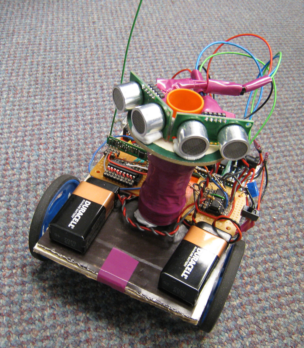
In an attempt to make the project extra interesting, we took a rather unconventional approach and decided to build the radio-controlled robot with only three wheels–two front and one rear. The two front wheels would be each driven by a DC motor, whereas the rear wheel merely serves as a point of support to the frame of the robot. The autonomous component of The TriWheeler would come from the use of detection sensors and an accompanying algorithm that helps the unit avoid oncoming obstacles.
Logical Structure
Introduction
The TriWheeler is a radio-controlled robot with three wheels. The lack of the fourth wheel is far from the only thing that renders it distinctively different from typical radio-controlled units. In addition to the capability of being freely controlled with a remote control, The TriWheeler has a smart autonomous mode that allows the unit to move freely without running into major obstacles. Furthermore, The TriWheeler features 3 speeds and the cruising speed could be easily adjusted using the remote control on the fly.
High Level Design
Inspiration | Logical Structure | Standards
Inspiration
The idea of our project stems from the concept of an autonomous vehicle. Having closely followed the 2007 DARPA Urban Challenge (Cornell has a participating team and did quite well), it is apparent that a future of driverless cars is soon upon us. With a deadline approaching in 5 weeks and a limited budget, certainly anything close to that extend is improbable and highly unrealistic. We decided to pursue a similar concept on a much, much smaller scale instead. A radio-controlled robot seemed reasonably doable and was eventually chosen.
In an attempt to make the project extra interesting, we took a rather unconventional approach and decided to build the radio-controlled robot with only three wheels–two front and one rear. The two front wheels would be each driven by a DC motor, whereas the rear wheel merely serves as a point of support to the frame of the robot. The autonomous component of The TriWheeler would come from the use of detection sensors and an accompanying algorithm that helps the unit avoid oncoming obstacles.
Logical Structure
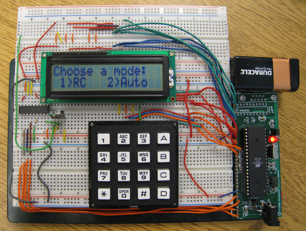
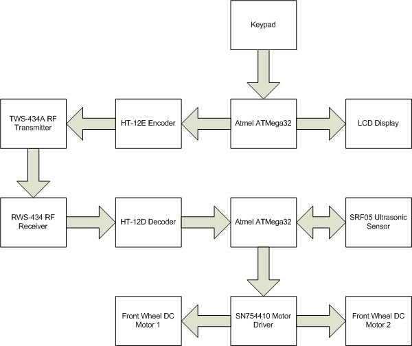
The project has two major parts: the remote control unit and the receiver unit. The keypad of the remote control unit serves as the single input device; it controls the movement of robot under manual mode and is also used to navigate the interface of the remote control displayed on the LCD. Commands from the keypad are processed by the ATMega32 microcontroller unit, encoded and then transmitted by the RF transmitter. On the receiving end, received commands are decoded, processed by the microcontroller and translated to a series of corresponding movements. Under the autonomous mode, sensors activate and detect continuously at timed intervals. At the same time, their outputs are monitored by the detection algorithm that is ran on the onboard microcontroller. The algorithm acts accordingly and ensures the robot stays clear of obstacles.
Standards
The TWS-434A RF transmitter used in the unit complies with FCC standards and does not interfere with other licensed transmitters. It transmits within the acceptable range of frequencies specified in part 15 of the FCC.
Implementation
Motor Control
Since we decided to build a robot with two front wheels each with its own DC motor, we were presented with a number of options to implement the steering system. Eventually we figured it is probably the best to run both motors simultaneously in opposite directions. This scheme provides us with an extremely responsive steering system. It later proved to be quite valuable as it complements certain shortfalls of our detection algorithm, especially when the TriWheeler is set to move at the high-speed mode.
Much of the motor control was accomplished through the use of the SN754410 Quadruple Half H-Bridge IC, essentially a single package that contains four h-bridge switches. The SN754410 package is particularly attractive to our project because not only it is cheap and readily available, the use of it dramatically reduces the amount of motor control circuitry that we need to build onboard the receiver unit. Furthermore, the use of h-bridges allows us to drive the DC motors conveniently in both clockwise and counterclockwise directions. Each half h-bridge contained in the package is capable of driving one DC motor in a single direction. In our implementation, two half h-bridges were used in conjunction with each other to provide bidirectional motion control.
Each half h-bridge contained in the SN754410 package has an nA input and an nY output. The nY outputs of a pair of half h-bridges are connected to the positive and negative inputs of the motor. The activation of either nY pins would trigger and start the motor. The direction of turning depends on the polarity of the motor pin that was connected to. This scheme allows the TriWheeler to move in forward and backward directions. To steer the TriWheeler sidewise, we manipulate the outputs of the half h-bridges such that one motor moves forward while the other moves backward. The output value of half h-bridges is controlled by the nA pin. The following table illustrates the four combinations of nA values as well as the resulting operations.
Parts List:
| PART | QUANTITY | UNIT COST | TOTAL COST | SOURCE |
|---|---|---|---|---|
| ECE 476 Prototype Board |
2
|
$5.00
|
$10.00
|
ECE 476 Lab
|
| 16 MHz Crystal Oscillator |
2
|
$0.00
|
$0.00
|
ECE 476 Lab
|
| 9-Volt Battery |
3
|
$2.00
|
$6.00
|
Cornell Store
|
| DIP Socket |
6
|
$0.50
|
$3.00
|
ECE 476 Lab
|
| SIP/Header Socket |
182
|
$0.05
|
$9.10
|
ECE 476 Lab
|
| Atmel ATMega32 |
2
|
$8.00
|
$16.00
|
ECE 476 Lab
|
| LCD Display |
1
|
$8.00
|
$8.00
|
ECE 476 Lab
|
| Keypad |
1
|
$6.00
|
$6.00
|
ECE 476 Lab
|
| Switches |
2
|
$0.00
|
$0.00
|
ECE 476 Lab
|
| Resistors, Capacitors |
various
|
$0.00
|
$0.00
|
ECE 476 Lab
|
| Whiteboard |
1
|
—
|
—
|
Owned
|
| Small Solder Board |
2
|
$1.00
|
$2.00
|
ECE 476 Lab
|
| TWS-434A RF Transmitter |
1
|
—
|
—
|
Donated
|
| RWS-434 RF Receiver |
1
|
—
|
—
|
Donated
|
| HT-12D Decoder |
1
|
$1.90
|
$1.90
|
Rentron
|
| HT-12E Encoder |
1
|
$1.90
|
$1.90
|
Rentron
|
| SRF05 Ultrasonic Sensor |
2
|
—
|
—
|
Donated
|
| SN754410 Motor Driver |
1
|
$1.65
|
$1.65
|
Rentron
|
| DC motor |
2
|
—
|
—
|
Owned
|
| Back Wheel |
1
|
—
|
—
|
Scrap
|
| Front Wheel |
2
|
—
|
—
|
Owned
|
| Cardboard |
1
|
—
|
—
|
Scrap
|
| Total |
$65.55
|
For more detail: TriWheeler robot Using Atmega32