Introduction
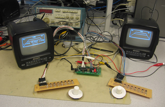
Our final project is a two-player, 3D, air hockey video game using non-contact paddles.
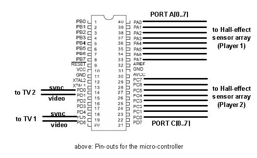
A single Atmel ATmega32 microcontroller on a prototype board is used to compute puck dynamics, decode inputs from two Hall effect sensor arrays, compute paddle-puck interactions, perform perspective projections from 3D to 2D for each player, and generate two different video signals. Two television sets are used so that each player can see the playing field from the player’s own end, with a three-dimensional perspective. Each player can see his or her own paddle, together with the opponent’s paddle and all paddle movements. The players control their paddles using Hall effect sensor arrays, which do not require contact and are frictionless. The video signals are in NTSC format at 60 frames per second (interlaced). The various calculations are optimized so they will not affect video signal generation, preventing artifacts from appearing on-screen.
The actual air hockey game requires an air hockey table, two paddles (or mallets), and a puck.A typical air hockey table consists of a large smooth playing surface, a surrounding rail to prevent the puck and mallets from leaving the table, and slots in the rail at either end of the table that serve as goals. On the ends of the table behind and below the goals, there is usually a puck return. Additionally, tables will typically have some sort of machinery that produces a cushion of air on the play surface, with the purpose of reducing friction and increasing play speed1.This aspect is recreated in the game by not having any drag on the puck movement.
High Level Design
State machine
A state machine was created to implement the high-level design shown above. This state machine provides a choice between 1 and 2 player modes. It also pauses the game after each point and set, so as to show who scored. A victory screen is also displayed when a player wins 3 sets. Subsequently, the game returns to the initial start-up screen.
Program / Hardware Design
Driving Two TVs with Interlacing
Dr Bruce Lands video code, which writes every line in the video buffer array twice at 60 frames per second, is modified to drive two TVs with two different contents. The figure below shows the line sequence of each frame in the original code:
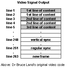
We take advantage of the redundancies in the line sequence to add in contents for another TV. The motivation behind this is that, NTSC format, consisting of only 30 interlaced frames per second, is still able to generate video without flickering. By using a similar arrangement of line sequence, we are able to drive 2 TVs at 30 interlaced frames per second using the arrangement..
Video line sequence A and B alternates to gives 30 interlaced frame per second for EACH of the two TVs. In the code, video line sequence A is given the value 1, and sequence B the value 0. At each interrupt (beginning of each video line from line 1 to 263), the micro-controller outputs to TV 1 (via PORT D.5 and D.6) if it is at an odd line in video sequence 1, or at an even line in video sequence 0. Otherwise, it outputs to TV 2 (via PORT D.0 and D.1).
Two video buffer arrays are used to store the contents for the two TVs. With only 2kb of SRAM, we have to limit the size of our video buffer to 800 bytes each. This still gives a reasonably sized playing area. Basic drawing tools such as videoline(), videopt(), videoputsmalls() are duplicated to allow us to edit the other video buffer.
Perspective Projection2
The perspective projection corresponds more closely to the way a human observer perceives a 3D scene: objects far away appear smaller and closer together. Mathematically, the projection transformation converts a point (x,y,z) into (x’, y’), the image point where the 3D point appears on the output medium (TV screen). The figures below show how the 2D playing field used in our puck dynamics calculation would look like in the perspective projection. The ultimate goal of the transformation is to convert the playing field coordinate system into each player’s TV screen coordinate systems.
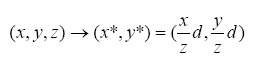
To begin the transformation, let’s consider the simple scenario where the viewer is at the origin, and the plane of projection is at z=d. The original coordinates (x,y,z) will be transformed to
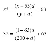
When the viewer is not at the origin, all we need to do is a simple translation. In our code, the x-axis of the playing field coordinate system is aligned with the x-axis of the TV screen coordinate system. The center of screen is at x=63, and this gives the x-coordinate of the viewer.
We next determine how we want the 200×126 air hockey table to look like on the TV screen. We decided that the far end of the air hockey table should look like it has half the width of the near end, while the length of the table must fit from y=13 to y=47 on screen. This allows us to find the value of d. Intuitively, we are asking the question: from how far should we view a 200×126 table such that its far end appeared as only half its near end?
One equation can be formed by looking at the projection of far left corner of the table with coordinate (x=1,y=200) (*To keep projection simple, the length 200 playing field runs from y=0 to y=200 instead of y=20 to y=220 used in dynamics calculation). The far left corner appeared on the TV screen at (x=32, y=13). The equation below is solved to yield d=200.
The equations of projections from the playing field coordinates to the TV screen coordinates for Player 1 are found to be:
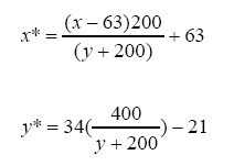
To view the playing field from the other side of the air hockey table, a similar transform can be applied. We can use the same coordinate system from Player 2’s perspective by performing a reflection about x=63 and y=120.
The equations of projections from the playing field coordinates to the TV screen coordinates for Player 2 are found to be:
To summarize, we perform the puck dynamics calculation on the playing field coordinate system. The position of the puck obtained at the end of each video frame is then displayed at the appropriate position on each player’s screen using perspective transformation. This gives both players the perception that they are watching the air hockey table from their own side.
Puck Management
The puck has an x and y position variable, an x and y velocity variable, and an age flag. The age flag keeps track of whether the puck has entered a goal, i.e. not returned by a player. When a new puck enters into play, the age flag is initialized to 1. The flag is set to 0 when any player fails to return it. Thus, the puck is removed from the game and not displayed. Subsequently, a new puck is initialized.
Optimization
Fixed point arithmetic is used here for positions and velocities, because animation involves fast loops and floating point arithmetic is too slow for small, 8-bit processors to handle, except when human interaction is involved. Fixed point representation uses numbers stored as 16-bit signed ints, with the binary-point between bit 7 and bit 8. This allows a dynamic range of +/- 127, with a resolution of 1/256=0.00396. Sign representation will be standard 2’s complement.
For more detail: Two-TV video air Hockey Using Atmega32