Summary of Unleash the Power of AVR Hardware: Build Your Own Calculator with Keypad Input
This lab guides users in preparing an AVR microcontroller for programming and debugging, followed by designing a 4-function calculator using a state machine. Key steps include constructing a breadboard circuit with 330 Ohm resistors, configuring the ATMega32 via AVR Studio (ISP mode, fuse settings), and uploading code to drive LEDs. The project utilizes a 4x4 keypad for input and demonstrates proper PORT/PIN register usage for hardware interfacing.
Parts used in the AVR Microcontroller Calculator Project:
- AVR Microcontroller (ATMega32)
- Breadboard
- Resistors (330 Ohms)
- LEDs
- 4x4 Keypad
- USB Cable
- Programmer
- AVR Studio Software
In this lab, we will be preparing our AVR microcontroller hardware for initial programming and debugging.
To get started, follow these steps:
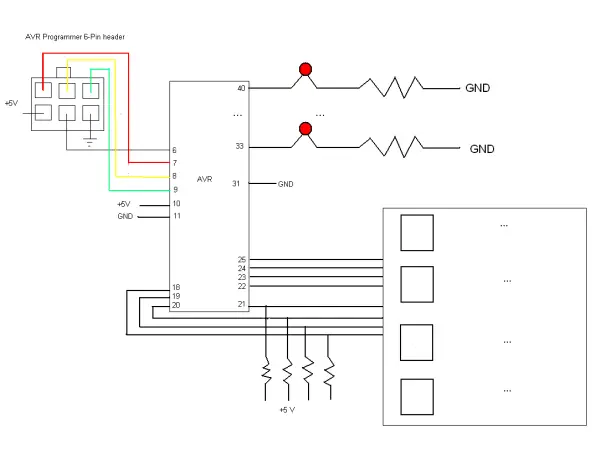
Construct the circuit as shown on your breadboard. This will allow us to interface our microcontroller with external components.
For reference on pin connections and specifications, consult the microcontroller’s datasheet. The datasheet is an essential reference for understanding the technical aspects of the chip. I recommend taking some time to explore the datasheet and familiarize yourself with its organization and contents. Having a working knowledge of the datasheet will serve you well as you progress through your microcontroller exploration this quarter.
By building the recommended circuit, we set the stage to begin programming our physical AVR device. Referring to the datasheet is important to properly connect components according to the microcontroller’s specifications.
All resistances are 330 Ohms.
SAMPLE CODE:
| #include “avr/io.h”
int main() { DDRA = 0xFF; while(1) { PORTA = 0xAA; } } |
Once the code above successfully compiles, select Tools->Program AVR->Connect to bring up the dialog box below. Ensure the below options are selected, and that your programmer is plugged into your machine via USB cable.
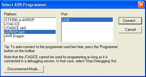
Click connect in the above dialog, and the below dialog should pop up. Ensure that the ATMega32 device is selected, and that ISP programming mode is selected.
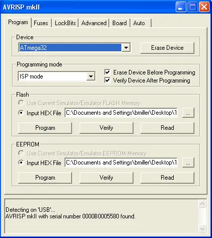
Click the “Board” tab and change the ISP frequency to 125 kHz. Then click “Write”.
Click the “Fuses” tab. Select “Int. RC Osc 8 MHz: 6 CK + 64ms” and ensure “JTAG Interface Enabled” is unchecked. Click “Program”.
Click the “Lockbits” tab and confirm “Mode 1” is selected for all options.
Go back to the main dialog page by clicking the “Program” tab.
Under the “FLASH” memory section, click the ellipses and select the .hex file built with your project, typically found in project_dir/default.
Click “Program” to transfer the code to the microcontroller for the first time.
Check your breadboard – you should now see some lights indicating the microcontroller is running your programmed code.
By configuring these options and programming the microcontroller, you’ve successfully interfaced with the physical device for the first time.
Part 2
You will design and build a simple 4-function calculator using a microcontroller and keypad input.
Your design must follow the state machine format provided in the lab instructions. A large portion of your grade depends on using this structure correctly.
Before writing any code, take time to fully design the state machine on paper. Embedded system design is the focus of this course.
Users will enter two numbers and select an operator (A-D) using the keypad. The output is displayed on LEDs.
Numbers are verified on the LEDs before/after selection of the operator and second number.
Pressing ‘#’ calculates and displays the result.
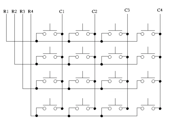
The lab will provide details on using a 4×4 keypad for input. Keys are detected by outputting a column pin low and reading the rows to detect button presses.
Follow all directions closely and design carefully before coding to succeed in this milestone lab. Proper planning is key.
Below is the start of a function that you should use to get input from the keyboard. You will need to complete the function. The function would be most helpful if it returned an index into the following conversion table.
SAMPLE CODE:
| /* You can have a conversion table to convert the key position into a
valid number which indicates the operator or operand value. For eg: the numbers 0 to 9 are valid operands and 100 to 103 denote addition, subtraction, multiplication and division respectively */
/* Note that your keypad has a different layout then the one used to design this lab, thus you will need to edit the conversion table to reflect your own keypad layout.*/
char conv_table[] = { 1, 2, 3, 100 /* add */, 4, 5, 6, 101 /* sub */, 7, 8, 9, 102 /* mul */, –1, 0, –1, 103 /* div */ };
int GetKey( ) { for(i=0; i<4; i++) { /* Set one column at a time to 0. */ PORTC = 0xff & ~(1<<i); for (j=4; j<8; j++) { /* Scan each row to see if a button was pressed */ /* Use i and j to index into conversion table */ } } } |
PORT/PIN Registers (PORT is for writing! PIN is for reading!)
When writing an output value to a port, use the PORT register.
For example, to write value x to Port C as output, use: PORTC = x
When reading an input value from a port, use the PIN register.
The PIN register reflects the real-time voltage level on the physical pins.
The PORT register only returns the last value written by the software. It does not account for any external hardware changes to the pin voltages.
For example, to read an input into variable x from Port D, use: x = PIND
This captures the current level on the Port D pins, accounting for both software outputs and external circuit connections.
Understanding when to use PORT vs PIN is important for proper microcontroller interfacing with external hardware via input and output operations.
-
What is the recommended resistance value for the circuit?
All resistances used in the circuit are 330 Ohms. -
How do you connect the programmer to the machine?
The programmer must be plugged into the machine via a USB cable before connecting. -
Which ISP frequency should be selected in the Board tab?
The ISP frequency should be changed to 125 kHz in the Board tab. -
What internal oscillator setting is required for the fuses?
Select Int. RC Osc 8 MHz: 6 CK + 64ms and ensure JTAG Interface Enabled is unchecked. -
How does the system detect button presses on the keypad?
Keys are detected by outputting a column pin low and reading the rows. -
When should you use the PIN register instead of the PORT register?
Use the PIN register when reading an input value to capture real-time voltage levels from physical pins. -
What character indicates the calculation command in the calculator design?
Pressing the # key calculates and displays the result.