
Summary of USB to Serial Breakout Board for Prolific PL2303SA
This article describes two low-cost, simple USB to serial (TTL) converter projects: one using the Prolific PL2303SA chip and another using the FTDI FT230XS chip. Both feature minimal component counts and include downloadable Eagle project files for assembly. The PL2303SA operates at 3.3V signal levels without an external crystal, while the FT230XS requires a specific resistor workaround to prevent suspend mode bugs in earlier revisions.
Parts used in the USB to Serial Converter Projects:
- Prolific PL2303SA USB to USART bridge chip
- FTDI FT230XS chip
- Resistor R1 connected to CBUS3 pin
- Eagle 6.x project files
This USB to serial (TTL) converter project is easy to build, it is simple and inexpensive. It is based on the PL2303SA USB to USART bridge from Prolific. The PL2303SA chip is not required an external crystal as the internal clock oscillator is continuously tuning up to USB bus frequency. Having chip in SO-8 packaging does not require special soldering skills to assemble the project. Please note: the TX and RX signal levels are 3.3 Volts.
If you would like to make your own, you can download the Eagle 6.x project files.
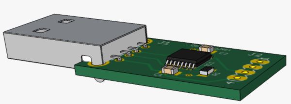
USB to Serial Breakout Board for FTDI FT230X
Another low component count USB to serial converter module is based on the FT230XS from FTDI Chip. The FT230XS is outfitted in SSOP-16 packaging. The first incarnation of FT230X chips got a nasty bug when the chip inadvertently goes into suspend mode triggered by certain byte sequences. The FT230X releases A, B and C were affected, see FTDI Chip TN_139 Technical Note. The resistor R1 connected to CBUS3 pin is providing workaround, keeping the chip awake. The Eagle projects files are here.
For more detail: USB to Serial Breakout Board for Prolific PL2303SA
-
What makes the PL2303SA chip easy to assemble?
The chip is in SO-8 packaging which does not require special soldering skills. -
Does the PL2303SA need an external crystal?
No, it uses an internal clock oscillator that tunes up to the USB bus frequency. -
What are the TX and RX signal levels for this project?
The signal levels are 3.3 Volts. -
How can you fix the suspend mode bug in early FT230X chips?
Connecting resistor R1 to the CBUS3 pin provides a workaround to keep the chip awake. -
Which versions of the FT230X chip were affected by the suspend bug?
Releases A, B, and C were affected by the issue. -
Where can you find the design files for these projects?
You can download the Eagle 6.x project files from the provided links in the article.
