Summary of Use a transistor as a heating element
This article describes a method to use an N-channel IRF540 MOSFET as both a heating element and temperature controller for biological samples. By leveraging the transistor's heat dissipation, the circuit eliminates separate heaters, operating within a 100°C limit. The design utilizes an LM35 sensor, TL431 regulator, and comparator logic to maintain samples between ambient and 45°C with hysteresis control.
Parts used in the Transistor Heating Element Project:
- N-channel IRF540 MOSFET
- LM35 Temperature Sensor (IC1)
- Digital Panel Meter (DPM)
- TL431 Shunt Regulator
- Comparator IC (IC2)
- Potentiometer VR1
- Potentiometer VR3
- Resistors R9 and others
- Switch S1
- LED Indicator
- Metal Block Sample Holder
- Thermal Grease
- Thermal Pad
It is common to use transistors for driving resistive heating elements. However, you can use the heat that a power transistor dissipates to advantage in several situations, eliminating the need for a separate heating element because most transistors can safely operate at temperatures as high as 100°C. A typical example is in a biological laboratory, in which the need for maintaining the temperature of samples in microliter-sized cuvettes is a common requirement. The space/geometry constraint and the less-than-100°C upper-temperature limit are the basic factors of the idea.
You can use an N-channel IRF540 MOSFET to directly heat and control the temperature of a biological sample from ambient to 45°C. Figure 1 shows a simple on/off-type control circuit in which an LM35, IC1, is the temperature sensor, whose output a DPM (digital panel meter) can display. IC2 compares the voltage that VR1 sets with the output of the LM35 to turn on Q2 accordingly, with the positive feedback through R9 providing a small amount of hysteresis. S1 switches the DPM between a set value and the actual temperature readout. You derive the reference voltage from a TL431 shunt regulator (not shown). The LED lights up when Q2 is on.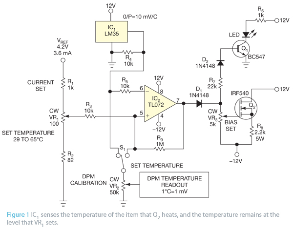
IC1 and Q2 thermally mount on the metal block that forms the sample holder; use thermal grease on both components for maximum heat transfer. Note that the mounting tab of the TO-220 package electrically connects to the drain, and you may need to insulate it from the cuvette with a thermal pad. Setting bias control VR3 for a Q2 current of 270 mA is sufficient to hold the cuvette at 45°C.
For more detail: Use a transistor as a heating element
- Can a power transistor be used as a heating element?
Yes, most transistors can safely operate at temperatures up to 100°C, allowing them to function as heating elements. - What is the maximum temperature limit for this project?
The upper-temperature limit for the described setup is less than 100°C, specifically maintaining samples up to 45°C. - How do you control the temperature of the biological sample?
An LM35 sensor and a comparator circuit compare the set voltage against the sensor output to turn the MOSFET on or off. - Which component provides hysteresis in the circuit?
Positive feedback through resistor R9 provides a small amount of hysteresis to the comparator. - How should the components be mounted for heat transfer?
IC1 and Q2 must thermally mount on the metal block using thermal grease for maximum heat transfer. - Does the mounting tab of the TO-220 package need insulation?
Yes, because the tab connects electrically to the drain, it may need insulation from the cuvette with a thermal pad. - What current setting is required to hold the cuvette at 45°C?
Setting bias control VR3 for a Q2 current of 270 mA is sufficient to hold the cuvette at 45°C. - What does the LED indicate in the circuit?
The LED lights up when the transistor Q2 is turned on.