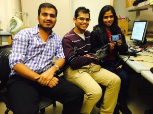
For our 4760 final project, we built a virtual bowling game interface on a black and white Television in which the ball can be controlled by the glove which has the flex sensors and the accelerometer attached to it. There are 5 flex sensors on the glove to detect the ball grasped and the ball released gestures. The accelerometer will provide the velocity with which the player bowls and the corresponding to this, the ball moves and shoots down the pins on the television. The total development cost is kept under $50 as per the project guidelines
We chose this project because we wanted to explore virtual reality domain and this particular application effectively execute all the things that we learned in the class and build an application in which all the functionality is controlled by the microcontroller. The bowling application was chosen because we found that there was effective use of both flex sensors and the accelerometer that fits right in the application.
High Level Design
Design Rationale
After couple of brainstorming sessions and considering all of our interests, we decided to base our project idea on Virtual Reality. Also, when we were going through previous years projects, we came across sign language translating sensor glove. This project was able to sense the hand gesture and map them from a sign language to English Alphabet. We thought it would be a great idea to map different gestures and use it as motion control for Computer. After consulting Professor, we figured mapping the gestures on a TV would be fairly easier and our work would be more around the microcontroller rather than software which would also help implement our knowledge of the Television interface that we learnt in Lab3. Hence, one of our teammate suggested that we could implement the bowling game as the application and use the hand gestures to play. We found this to be a great idea and started working on it right away.
Logical Structure
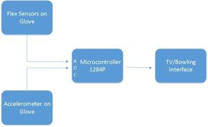
The flex sensor and the accelerometer are fixed to the gloves. The sensor readings are converted to a digital signal by the ADC on the microcontroller. These readings are calibrated and the action and the gestures during the duration of the play. The virtual bowling game interface is developed on the television. The video generated is a non-interlaced, black and white video that displays a Bowling alley the scoreboard. Based on the input of the player, the ball moves and knocks down the pins. To get the feel of a video game, Nintendo like sound effects is added to it. All the tasks of updating the video, reading the sensors and playing the music are done by the microcontroller.
Hardware / Software Trade offs
All the tasks in our program surrounded around the video code. We had to adjust all the tasks so that the updating video at 60Hz does not get affected by it. We could not use any other interrupts, we managed to fit in all the delays and the interrupts we needed in the Timer0 interrupt itself. But we dint face much problem because the sensors were read 60 times per second which was accurate enough for our application. We wanted to give an user interface that allows the player to enter his/her name , but this required use of UART which will slow down the video , hence we were not able to include it in our program. We spent most of the time working on the animation and we trying to make the game more realistic, hence we fell short of time to include the Bluetooth module that we had initially thought off.
Relevant Standard
Our project followed all legal and relevant standards of industry. The video signals are generated in NTSC format and are produced at constant rate. The video code follows the NTSC standard using 29.94 interlaced frames per second. Following the NTSC refresh rate and interlacing standards ensures that the video can be displayed properly on a NTSC-compatible TV. We also followed standards required by Sensors keep them operating at all times.
Hardware Design
Flex Sensor
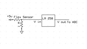
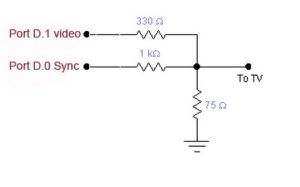
These sensors are basically variable resistors. They vary when they are varied in either direction linearly. The sensors obtained were Flx-01 H, which is a high resistance flex sensor .The sensor’s resistance did not vary according to the datasheet. It was supposed to be 10k ohms in the unflexed position, but at unflexed positin , the resistance was way too high to read and when bent it varied to 300k ohms on either side. The voltage divider circuit was designed as shown below. The value of the resistor chosen was 1M ohms .the output from the voltage divider circuit was given to a buffer LM238 due to its high resistance. The output of the buffer was fed to the ADC pins of the microcontroller. The flex sensors readings were highly unreliable, some dint work and some worked indifferently. But we managed to calibrate it accordingly and use it appropriately for our application.
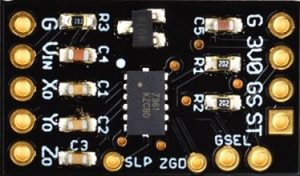
Accelerometer
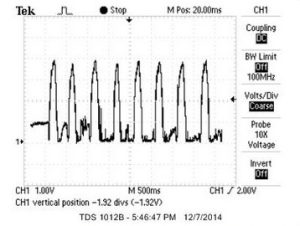
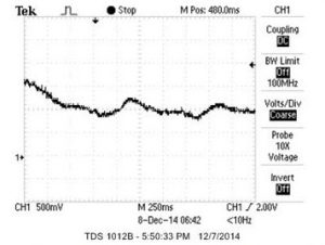
The accelerometer measures the acceleration forces. By measuring the amount of static acceleration due to gravity, we can find out the angle the device is tilted with respect to the earth. By sensing the amount of dynamic acceleration, we can find out and analyze the way the device is moving. In this project, we chose the accelerometer to provide different velocities to the ball. The accelerometer basically determines the acceleration at which the ball is being thrown. The accelerometer used here is Modern Device 3 Axis Accelerometer Module. It’s a tiny chip that has Freescale MMA7361 three-axis analog accelerometer. This chip includes a voltage regulator to provide the 3.3V to the MMA7361 and the 10nF capacitors on the outputs. Hence there was no additional circuitry required for it. We were able to get accurate readings by directly connecting the different orientation inputs (x-axis,y-axis,z-axis) to the ADC of the microcontroller by directly connecting the input to the Vcc of the microcontroller. The testing of the accelerometer was done using the using the oscilloscope. The screenshot of the oscilloscope is as shown in figure 5.
Television
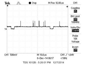
The LCD TV requires two signals namely the Sync and Video. The Video signal contains the information to be displayed on the TV. Sync signal synchronizes the frame display in regular and inverted fashion to display each frame on the TV. The combined input as shown in the figure 6, is provided to the LCD to display the video signal synchronized to display frames at 60Hz.To test the setup, we connected the circuit to the micro controller and loaded the LCD TV test program on the micro controller. Upon the power up, the microcontroller displayed the basic LCD TV testing signals on the TV. To make sure of the signals, we observed the combined TV signal on the oscilloscope to validate the same. The signal found to be in sync and generated required LCD TV.
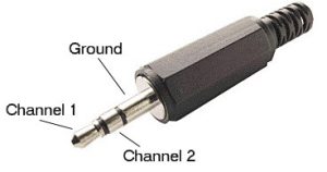
Audio
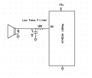
The connection to the speaker is given by clipping the crocodile pins to the audio plug. The Channel 1 is connected from the output of a low pass filter and MCU ground is connected to the ground. Pin B3 will produce the audio note, which is then passed through a low pass filter and connects to the speakers. This smoothens the signal and reduces the noise.
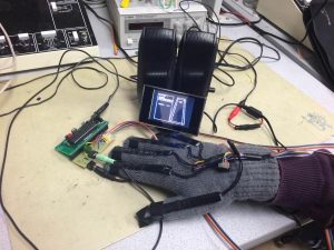
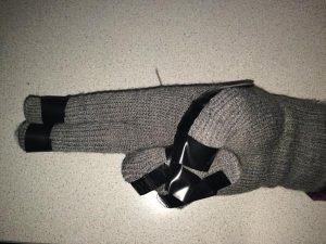
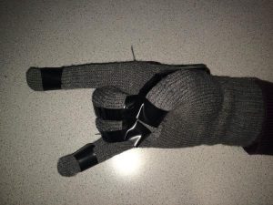
Glove Unit
The Glove unit consists of the flex sensors and the Accelerometer circuits. There are carefully mounted on the gloves to obtain accurate hand gestures. The Game is played by wearing the gloves that has both the flex sensors and the accelerometers mounted on it. The Ball can be controlled by the player with the help of his/her gestures. The gestures and the motion of the hand are recognized and give corresponding velocity to the player.
Software Design
A Bowling Game contains 10 Sets of Games. Each Set will contain two Games. In each game, the player tries to knock down pins at the end of the lane. The number of pins knocked out will be counted towards score. If the player manages to knock out all 10 pins in the first game of any Set, the play is called a STRIKE. If the player manages to knock down all 10 pins in both games combined together in any particular Set, the game is called a SPARE.
As described in the previous sections, the Virtual Bowling application receives the inputs from the hand gestures received from the flex and accelerometer sensors. While the flex sensors help to determine if the ball is gripped or not to identify when the ball is launched, the accelerometer provides the direction and speed to the ball. The speed with which the ball is thrown is determined by the speed of the hand movements and the angle of the throw provides the direction to the ball. These are further explained in detail in later sections. The bowling application is displayed on a LCD video display with the background audio music played through the speakers.
Finite State Machine
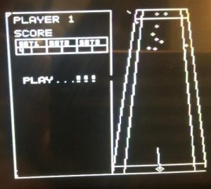
To start with the bowling game, the program first draws the layout of the bowling lane and the score board and initializes all timers and interrupts. The bowling game flow is guided through the Finite State Machine (FSM). Upon all initializations, the program traverses through the FSM to control the flow of the game. The software design is better explained with the Finite State Machine (FSM) shown in figure 11 below.
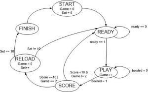
START : The Virtual Bowling application starts with START state where it performs all initializations and resets all the variables and flags. Once all the initializations are done, the state transitions to READY state.
READY : In this stage, the application asks the gamer if he is ready to play the game. The user will have to gesture the Ready signal shown in the Figure 12 below to indicate that he is ready to play the game.
This gesture is recognized by using flex sensors. To determine the gesture, first, voltages across flex sensors are read from all 5 fingers of the hand through the ADC. Then these values are analyzed to determine which fingers are bent and which are not. Finally, these are logically combined to determine the gesture making sure that the required fingers are bent and others are straight. Once the Ready Gesture is determined, the application decides if the bowling pins needs to be reset or no. The pins will be reset for the new Set or retained in the previous positions for the second Game in the same Set. Finally, the state is changed to PLAY.
PLAY : In the PLAY state, the program waits till the user Grips the ball. The gesture to grip the ball is shown in Figure 13 below
As soon as the user grips the ball and holds fingers in the same gesture, the ball will be gripped. While the ball is gripped, the user can direct the ball through direction arrows by rotating his wrist. If he turns his wrist clockwise, the direction changes towards right and if the user turns his wrist to the left, the direction of the ball changes to the left. The direction arrows are shown in figure 14 below.
To launch the ball in the direction he has selected the user will have to release his fingers from the ball gripped position. The ball will then be launched in the direction the user pointed with the velocity proportional to the speed of the hand of the user while launching the ball. When, eventually the ball collides with the bowling pins, the pins and ball will be deviated in different directions as guided by the vector dynamics for collision. During these collisions, in order to prevent the ball from coming back in the reverse direction, the velocity for ball in y direction is not updated but only the velocity in x direction is updated. The pins will gain the velocity from the collisions and move in the directions as guided by the vector dynamics. As soon as the pins move out of the stage, their velocities are reset to zero keeping the ball within frame in their current locations. Only these balls which move out of the stage will be counted towards the score. Finally, when the ball moves out of the stage, the game is over and the state transitions to SCORE.
SCORE : In this state, the number of pins pushed out of the stage are counted as the score and displayed on the screen. In the first game, if player pushes all 10 pins are out of the frame, its called a STRIKE. If the player retains few pins on stage in the first game and manages to knock them out in the second Game od the same Set, the score is said to be a SPARE. If user hits a STRIKE in the first game of a Set, the score board displays an “X” and transitions the state to RELOAD skipping the next Game in the same Set. If the user doesn’t score a STRIKE in the first Game of the set, the program will then move to READY state giving a second Game to the user. If the player hits a SPARE in the second Game, the score board displays a “/”. After the second Game, irrespective of score, the program moves to the RELOAD state resetting all the pins for the next Set.
RELOAD : In the Reload state, the Game and Set values are incremented appropriately. If all Sets are played, the program will switch to FINISH state. If there are any more Sets remaining to play, the program switches the state to READY state.
FINISH : Once all the Sets are played out, the program reaches FINISH state. In this state, scores from all previous games is summed up and displayed on the Screen. The program will be switched to START upon resetting the microcontroller.
Interfaces
Flex Sensors : The flex sensors when left straight with no pressure to bend them will offer resistance of the order of Mega Ohms. When these flex sensors are bent, the resistance of the same will come down to the order of few hundreds of kilo ohms. The degree of bending will determine the decrease in the resistance offered by the flex sensors. Thus there is a huge change in the flex sensor resistance that is used to identify if the finger is bent or not.
Analog-Digital Conversion : The Output of the voltage divider circuit driven by the flex sensors and the accelerometer output is fed to the input of the ADC of the Microcontroller. A prescalar of 128 is set, so that the system clock is reduced by the same factor. ADCSCRA starts another conversion and enables the ADC. The ADMUX register selects the input channel and sets the reference signal. Since the voltages from the sensors were varying from 0 to 4V, we set the Reference voltage to 5V i.e the Vcc. In the program, various sensors needs to be read at different times to compute various conditions and gestures. Thus, the sensor values are read through the function getData() which loops through all the sensors and converts the read data to digital using the on-chip ADC.
TV : In this section, we describe the interface software for the LCD television. The LCD TV follows the NTSC standards for the video display. As per the NTSC standard, the video is updated at 60Hz. To update the video at 60 Hz sharply, a timer interrupt is enabled to perform the video update at 60 Hz. Timer 1 is made use of for this task. Since this game involves the collisions between the ball and pins, we have employed the vector dynamics to demonstrate the collision effects. The vector dynamics was developed to determine the post collision velocity and position for each of the balls. The relative position and velocity vectors for the ball and pins under collision were determined with the following equations.
The delta change in the velocity of the ball and pins were determined by the following equation.
The balls and pins were then tested for this vector dynamic implementation for the visual ball collision effect deflecting each ball into different direction. The position and velocities varied for both balls under collision giving the visual effect of the collision between the balls. In the program, the video update for the TV is done by the updateVideo() function. This function executes a loop at 60Hz. During each iteration, it reads the sensor values, performs various checks and updates the video for the game. Once the game is over, it execution exits out from the function and moves ahead to the SCORE state in the FSM.
Audio : The Audio jack was interfaced to play a background music while the user is playing the game. To implement the software interface for the audio jack, an audio note is read and output to the audio jack during every video frame update. Thus, essentially, the audio music was updated at 60 Hz. To obtain this frequency timer, the prescalar was set to 256 to generate a sampling frequency. Hence the audio is being updated 60 times per second. Every time the line count reaches the screen bottom, the audio gets updated. In order to make the sound little different from the demo sound, the design added a delay of 2 seconds between notes. As described above, the audio is updated at 60Hz. This is performed within the updateVideo() function. During each video frame update, one audio note is read and output to the audio jack. Thus a continuous background music will be sounded while playing the game
Program Listing
int main() : The main function is the first function to start the program execution. In this function, all the initializations are performed and then the FSM is called to take over the execution flow.
void init() : In this function, all the settings pertaining to ADC, LCD, TV, FSM, audio are initialized. This function also calls the draw layout function that draws the layout for the Virtual Bowling game.
void drawLayout() : This function draws the layout for the bowling lane and draws the score board. It also displays the player name. And finally draws the frame across the player details, score board and message box.
void FSM() : In this function, the bowling game is traversed through the FSM defined for this application. This function traverses through each state of the FSM and controls the game flow from start till the end.
char readyCheck() : This is a blocking function that waits till the player gestures the ready symbol to play the game. This function reads all the sensors data and determines if the player has made the Ready gesture. As soon as the ready gesture is made, the function returns 1 indicating that the ready gesture is made and the FSM is ready to move to the PLAY state.
void resetPins() : This function is called when the FSM identifies that all pins needs to be reset. This function initializes all the pins and ball with predetermined positions and with zero velocities and then finally draws all the pins and ball to display them on the score.
void updateVideo() : As soon as the program receives the Ready gesture, the program moves to the PLAY state and calls updateVideo function. This function is also a blocking function. This function waits till the ball is gripped. Once the ball is gripped, it keeps updating the direction and speed of the ball. Upon the release, this function launches the ball in the direction guided by the arrow and with velocity determined by the hand speed. Once the ball hits the pins, it reinitializes the velocities of each pins and ball with speed and positions determined by the vector dynamics. Thus this function performs the vector dynamics between all pins and ball and updates the video. Once the ball goes out of the stage, the function returns meaning the end of the game.
char isBallGripped() : This function determines if the ball is gripped or not. This function implementation is similar to the readyCheck function as both reads the flex sensor values via ADC and determines the gestures. This function returns 1 if the ball is gripped and returns zero otherwise.
int readX() and int readY() : These functions read the accelerometer values in X and Y directions appropriately. Then, converts the analog position representations into digital and returns the digital values for the position of the ball.
void get_data(void) : Similar to the above mentioned readX and ready functions , this function reads all the flex sensors and stores the values of each sensor for further processing.
void displayScore(char gameScore) : This function determines the score of the game and updates the same on the score board in the correct windows.
char getGameScore() : This function is called within the displayScore to determine the score of the game. This function processes the positions of all the pins and determines pins which are out of boundary.
void draw_pin(char x, char y, char c) : Each pin is made of 4 points on the LCD TV screen. This function can both draw or remove a pin provided the position of the pin.
void drawball(char x, char y, char c) : This function draws the ball in a rhombus shape provided the coordinates of the ball is provided.
enum state : This enumeration defines the state of the FSM which is used throughout the program to control the game.
ISR(TIMER1_COMPB_vect, ISR_NAKED) : This ISR puts the MCU to sleep just before the CompA ISR goes off. This is needed to synchronize the ISR for sync generation accurately during every frame display. Kindly refer to the section 6.4 for detailed implementation of this function with comments.
ISR (TIMER1_COMPA_vect) : This is the sync generator and raster generator. It MUST be entered from sleep mode to get accurate timing of the sync pulses. Kindly refer to the section 6.4 for detailed implementation of this function with comments.
void init_lcd(void) : This function clears the LCD and initialization the same for any display.
int multfix(int a, int b) : This function implements fixed point multiplication.
char video_set(char x, char y) : Returns whether given point was set or reset.
void video_putsmalls(char x, char y, char *str) : Displays small charcaters
void video_puts(char x, char y, char *str) : Displays string in large characters
void video_putchar(char x, char y, char c) : Displays a single character
void video_line(char x1, char y1, char x2, char y2, char c) : Displays a line with given coordinates
void video_pt(char x, char y, char c) : Displays a point at the given coordinates
Results
Speed of Execution
The execution speed of our design basically limited by the Video updating rate which is 60 Hz. There is no observable flicker on the TV screen. There are also no video artifacts at any stage of the game. The Sensors output on ADC pins are read 60 times a second which is still higher than hand movement of humans. The music sounds are also generated at the same frequency. The direction arrow movement of the ball is smooth as the hand is rotated in either direction.
Accuracy
The background music generated is smooth and of good quality. In the beginning, we were having difficulty mapping the sensor output to virtual domain but after some efforts, we were able to calibrate them accurately. The flex sensors output are very much accurate to distinguish between folded and straight fingers. Ball directions are easily determined by hand rotations in left and right directions using Accelerometer. Since video is updated 60 times a second, no flicker is observed on the screen. The ready, play and bowl actions are accurately detected by the program.
Safety
The glove is insulated properly so that there is no direct contact between sensors, PCB and User. There is no other safety concern in our project.
Interference with other peoples design
There is no interference with other peoples design because of our device as it uses only flex sensors and accelerometer output.
Usability
For usability, we strongly encourage everyone to follow the gestures set for ready and play actions. This device is usable to anyone who is aware of the Bowling game and able to put gloves in their hand and perform certain gestures to play game. It may take some time to get used to the hand gestures for different parts of the game but once you are comfortable, you are going to enjoy it. People can’t move their hands and wrists will not be able to play this.
Conclusions
Results vs Expectations
At the beginning of our project, we wanted to create a complete bowling game with 10 frames. In bowling game player gets two opportunities to knock 10 pins in each frame and last frame may be comprised of 3 rolls(bonus rolls), making the total possible maximum score o 300. But due to space limitations on the TV screen and time constraints we are using only 3 frames game and maximum score one can achieve is 50(20+20+10) that is 3 consecutive strikes. We were able to add all the functionalities of a bowling game except for the scoring system. We added an extra feature where we can change the direction of ball even after launching it on the track. The hand rotation and ball gripping can be used to change the direction of ball before touching the gutter or pins. We also added the music which we hadn’t thought of during our project proposal.
Overall we were able to meet all the functional requirements of the game design except for the score and also added music which gives you a nice gaming experience and unlike other bowling games, scoring strike in our game is very tough. Try it!
Future Work (Room for improvement)
We would like to complete the scoring part of the game by displaying them vertically. Currently we are displaying them horizontally. We also want to add music for pin and ball collision to make it distinguishable from background music. Some flex sensors were very delicate and got damaged easily, so we need to be careful while using or calibrating them.
Standards
Our project followed all legal and relevant standards of industry. The video signals are generated in NTSC format and are produced at constant rate. We also followed standards required by Sensors keep them operating at all times.
Intellectual Property Considerations
The hardware design of this project was performed without using any others design or intellectual property. We designed the whole sensor mapping and interfacing system from scratch. The software we wrote combination of our and Bruce Land’s code from previous labs. We utilized Video signals generation code written by Bruce Land for Video Game Lab and added our logic for required video format on screen. Ball-pin dynamics was inspired by Bruce Land’s ball-ball dynamics in the same lab. We also used lcdlib.h and lcdlib.c to use LCD for debugging purposes which is written by Scienceprog.com for Atmel AVR series MCUS.
We did try to reverse engineer the code written by Bruce Land to generate the sound in Video Game Lab. This project was successful because of the motivation we got from Bruce Land’s video generation in Lab 3. It wouldn’t have been possible to finish this project in time without that and also LCD code was very helpful for debugging. As a result, we want to forgo any patent opportunities and leave our work as a open-source basis for any future student or hobbyist projects. No Non-disclosure forms were signed during duration of this project.
Ethical Considerations
During the 4 weeks duration of our project, we constantly complied with IEEE code of ethics. While brainstorming about the idea of this idea, we made sure that it was original and did not unfairly copy any existing project. During the design and implementation of our project, we kept the safety and welfare of the user in mind. While construction, we constantly checked for short circuit and corrupt components and made sure all the components are properly insulated. We also insulated all exposed components by either electrical tape or hot glue. Since we were using the space shared by other lab groups as well, we made sure that we keep the place clean and put all the components on their respective locations. All the data that we used are realistic and were obtained by our experiments and calibrations and we used them without cheating.
A comprehensive list of ethics we followed can found on IEEE website.
Legal Considerations
There is no legal considerations involved in this project.
Source: Virtual Bowling