Summary of VOICE CONTROLLED HOME AUTOMATION SYSTEM
This project creates a voice-controlled system to remotely toggle multiple power sockets across different rooms. Using a Raspberry Pi as the core unit and ATmega32 microcontrollers for remote units, the system processes voice commands via the Jasper engine and transmits signals wirelessly. While the design successfully met its objectives, testing revealed that ambient noise and distance significantly impact performance reliability.
Parts used in Voice-Controlled Power Socket System:
- Raspberry Pi microprocessor
- ATmega32 microcontroller
- TRM-418-LT (TXM-418-LC) wireless transceiver chip
- Relay board
- Logitech Webcam microphone
- AC-DC converter
- Jasper voice recognition software
- Resistors and capacitors for power filtering
- Transistors for relay control
- Ethernet, HDMI, and USB ports for connectivity
Abstract
This project develops a system capable of remotely toggling multiple power sockets across various rooms using specific voice commands. This enables convenient management of diverse electrical devices through voice control. While the project has fulfilled its verification requirements and successfully attained its design objectives, improvements in managing noise and distance might be necessary for future development.
1. Introduction
In today’s households, there is a growing need for a voice-activated switch system that can efficiently oversee various electrical appliances through voice commands. Presently, available voice-controlled products are restricted to controlling a sole power socket. This limitation has inspired us to develop a system capable of remotely managing multiple power sockets across different rooms, enabling specific voice commands for each socket. This initiative aims to establish an automated and convenient home setting.
The report will outline the project’s segmented components, detail the design process, specifications, validation procedures, estimated expenses, and draw final conclusions. Included below are the top-level block diagrams and their corresponding descriptions.
Core Unit
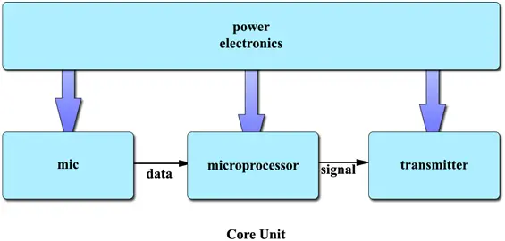
Diagram 1 displays the Core Unit’s block structure. The proposal includes a setup within the Core Unit featuring a microcontroller, relay, and power socket linked to the microprocessor, akin to the remote unit but utilizing local wired connectivity. However, during the subsequent design phase, it was determined to eliminate this setup. Given its redundancy with the remote unit’s functionality, the wire-controlled power socket was deemed unnecessary and hence removed.
Microphone
Microphone captures users’ voice commands.
Microprocessor
The Raspberry Pi microprocessor gathers data and conducts initial phase analysis. Subsequently, it transmits this data to an online engine for further examination and receives plain text in return. This text is then analyzed to issue commands to various units. Additionally, the microprocessor is equipped with an Ethernet port, enabling communication. The Raspberry Pi also features HDMI and USB ports, facilitating connections to a keyboard and monitor for users to modify settings.
Power Electronics
The power electronics circuit comprises an AC-DC converter equipped with resistors (R) and capacitors (Cs) designed to transform alternating current from a wall outlet into a stable and pure 5V power output.
Transmitter:
The transmitter wirelessly accepts the signal from the microprocessor and transmits it to the remote unit.
Remote Unit
Diagram 2 depicts the block diagram of the Remote Unit.
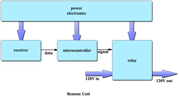
Receiver
The receiver picks up the signal transmitted wirelessly from the core unit.
Microcontroller
A cost-effective ATmega32 microcontroller is employed to handle the signal received from the core unit and issue commands to the relay. We utilize libraries to either receive data or create our own functions for sampling and conversion. Once the data is converted into commands, it is transmitted to control the relay. Additionally, a switch is incorporated to activate or deactivate the voice control feature.
Relay
The relay accepts instructions from the microcontroller to toggle the socket’s power on and off.
2. Design
This portion delineates the design choices, options, and specific intricacies of every individual block.
Design procedure
Power electronics
The initial approach to designing the power circuit involved creating the entire power electronics setup from the ground up, encompassing components like the transformer (inductors), rectifier, filter, and regulator. Through HSPICE simulation, the observed ripple in the produced 5V DC was minimal and met expectations. Nevertheless, the self-constructed inductor-dependent transformer was susceptible to manufacturing flaws and displayed unforeseen instability in performance. Given the paramount importance of ensuring a consistently stable power supply for delicate components like the transmitter and receiver, we ultimately opted to employ an AC-DC converter and fashioned the power circuit around this integrated chip.
Microprocessor
We opted for the Raspberry Pi among various microprocessors due to its comprehensive array of ports that cater to our needs, encompassing connections for microphone, speaker, keyboard, Internet, and screen. Additionally, its compatibility with the Rasbian OS enables us to operate the voice recognition software, Jasper, which is integral to our project. Alongside Jasper, we’ve developed our control program, working in conjunction with Jasper to generate control signals based on voice commands.
The software aspect serves as a potential safeguard in case of any hardware design shortcomings. In our design strategy, we’ve formulated two plans. Firstly, to establish bidirectional communication where the core device dispatches commands to the remote, and upon receipt, the remote device sends acknowledgment back to the core. Secondly, we’ve devised a system to repeatedly transmit a command from the core to the remote. Although this limits the command types to fundamental ON and OFF instructions, it ensures that the remote will reliably receive the command even in a noisy environment.
Transmitter and receiver
The TXM-418-LC, enabling wireless communication in both directions, serves as both a transmitter and a receiver. An alternative approach involves employing separate single-direction transmitter and receiver chips. Nonetheless, due to the potential for future advancements allowing feedback from the remote unit to the core unit, we opt for the bi-directional chip.
Microcontroller
We opt for the ATmega32 to handle the control signal from the microprocessor due to its affordability and ease of programming and testing using the Arduino shell.
Microphone
The voice recognition performance can be influenced by the microphone’s quality. Therefore, after completing the voice recognition process, we conduct tests on multiple microphones. We opt for the Logitech Webcam’s microphone due to its superior features, including the longest voice pick-up distance and exceptional clarity.
Relay
A relay board is utilized to enable the control of numerous power sockets, allowing for their activation and deactivation.
Design Details
Power electronics

Figure 3 depicts the outline of power electronics. As stated in the trm-418-lr datasheet [1], “It is operable with a power supply provided the noise remains below 20mV. The modulation of the transmitter can be impacted by power supply noise; hence, ensuring a pristine power supply for the module is crucial during the design phase.” Our power supply exhibits a noise level of 50 mV-p2p, necessitating the filtration of the input Vcc. The trm-418-lr datasheet offers a basic filter, and the subsequent calculation validates if this filter meets the circuit’s requirements.
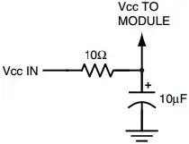
Figure 4 is a simple LPF implemented a resistor (10 Ohm) and capacitor (10 μF, tantalum capacitor). So the frequency respond is
????(????) = 1/jwc
R + 1/jwc
Simplify the equation
????(????) = 1
1 + jw × 10−4
????(????) = 1
1 + s × 10−4
As the datasheet lacks information on the frequency range impacting modulation, it assumes that noise significantly distant from the operating frequency (e.g., by a margin of 100) should adhere to the specified limits. Therefore, our objective is to ensure that at f = 4MHz, the circuit’s output exhibits noise levels below 20 mV.
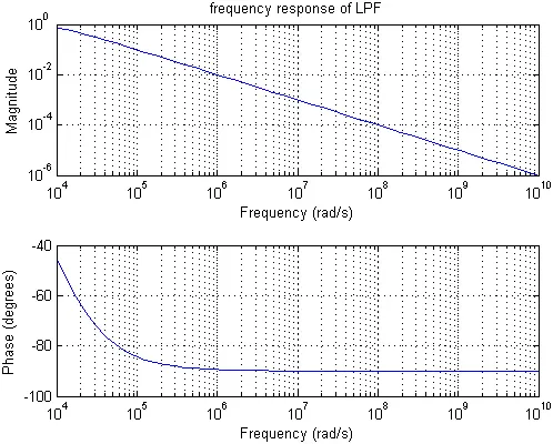
As we can see from figure 5, the magnitude of frequencies is around 10−2 which is far better than what is required.
To find the accurate result here is the equation
1
1i × 400 × 106
???? × 10−4
× 50 = 0.003 mV
which is far better than the 20mV requirement.
Microprocessor
The Jasper library locally examines the voice input to identify the presence of the keyword “jasper.” Upon detecting this keyword, the input is forwarded to an online voice recognition engine, which returns the corresponding text. Within my function, a text search is conducted to identify specific keywords like “Switch,” action verbs such as “turn on,” “turn off,” “toggle,” and the matching remote ID from local records. When all criteria are met, my function generates a 12-bit data package containing paired information and a specific command. This data is encoded using a Hamming 11-15 code, inserted into a shell, and transmitted via a transmitter.
On the receiving end, the program continuously monitors the output from the receiver, transferring it into a buffer. If the buffer aligns with the shell’s pattern, the data within the shell is decoded. The program initially checks the paired information; upon a match with the records, it proceeds to activate or deactivate a specific switch based on the received command.
At the implementation level, due to the absence of USART support in our transmitter/receiver chip, we devised our own serial communication protocol. Using the PIGPIO library, we manipulate GPIO pin 23 to produce alternating high and low digital signal outputs. After several tests, we settled on a baud rate of 500. Higher baud rates led to signal inaccuracies, while lower rates caused issues with chip handling. Employing the Hamming 11-15 code enables us to correct a single bit error and detect two-bit errors. The transmitted message to the remote unit includes the CPU’s serial number-derived 4-bit core ID, a 4-bit remote ID assigned to each microcontroller, and the remaining 3 bits reserved for commands. With a bit distance of 2, we can accommodate up to 4 distinct available commands.
Refer to Appendix C for the microprocessor software flowchart.
Transmitter and receiver
Figure 6 displays the layout of the transmitter and receiver circuits. The TRM-418-LT chip we’ve selected enables bidirectional wireless transmission of serial data. As per the datasheet specifications, three pins—PDN, TR_SEL, and DATA—need to be connected to the microcontroller to achieve the necessary functionalities. For our initial implementation stage, we plan to utilize Arduino and Raspberry Pi.
Regarding the software implementation, depending on the requirements, the DATA pin might necessitate connection to the tx/rx pin of Arduino (and Raspberry Pi) or other digital pins for transmitting and receiving digital data.
The TR_SEL pin facilitates switching the transceiver between its reception and transmission modes. When set to a high state, the TRM-418-LT operates in transmission mode. This functionality should be under the control of the microcontroller to enable a handshake between transmitters and receivers.
The PDN pin serves to activate a low-power mode, effectively powering down the device. A function could be developed to deactivate the transmitter within the core unit when not in use, thereby conserving power.
Microcontroller
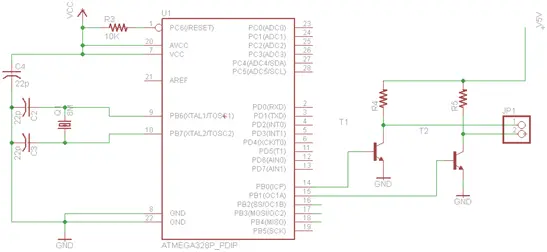
Figure 7 depicts the schematic of the microcontroller circuit. Utilizing the widely adopted ATmega32 microcontroller found in Arduino systems, we referenced the circuitry of Arduino [2] to structure the ATmega32 circuit. To address the voltage disparity between the relay and the microcontroller, transistors are integrated at the microcontroller’s output to regulate relay control.
Please refer to Appendix B for the comprehensive remote unit circuit, encompassing power electronics, the receiver, and the microcontroller.
For the microcontroller software flowchart, please consult Appendix D.
3. Design Verification
This portion covers the initial requirements, the verification plan, and the real-world testing of primary components within the finished project. Refer to Appendix A for the comprehensive requirement and verification table obtained from the design review process.
Power electronics
The objective in power electronics is to convert the 110V AC from a wall outlet to a stable 5V DC ± 0.02V. To confirm this transformation, the power electronics circuit is connected to the wall outlet, and a voltmeter is employed to assess the output voltage. In both the breadboard and completed PCB tests, a consistent measurement of 4.99V was obtained.
Transmitter and receiver
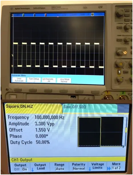
The transmitter and receiver must ensure stable data transmission from the core unit’s transmitter to the remote unit’s receiver. To confirm this transmission, we utilize a function generator to input a signal to the transmitter and initiate its transmission. Subsequently, we connect an oscilloscope to the receiver’s output to verify the signal reception. We conducted this test successfully at both the breadboard and completed PCB stages. Figure 8 illustrates that the received signal voltage registers lower than the transmitted signal. However, the test remains successful as the voltage remains sufficiently high to qualify as a logical high.
During the design review, we formulated lower-level tests for debugging the transmitter and receiver, which involved assessing the antenna voltage to confirm the transmission and reception of signals. Additionally, we conducted measurements of the signal’s frequency and gain, ensuring their alignment with the respective channels. As the module successfully cleared the higher-level tests, there was no necessity to execute the lower-level tests.
Microcontroller
The microcontroller’s task is to interpret received data into commands and subsequently transmit high or low signals to the relay based on these commands. To validate this functionality, we established a connection between the microprocessor and the microcontroller. We configured the microprocessor to dispatch commands to the microcontroller and verified that the microcontroller’s output corresponded correctly to either a high or low signal. During the initial breadboard stage, following successful verification of the transmitter and receiver, we conducted tests involving wireless communication between the microprocessor and microcontroller. The test was successful, and Figure 9 depicts the test results.
Microprocessor
The primary task for the microprocessor involves voice command recognition. To assess this capability, configure the microprocessor by integrating a microphone, screen, and internet connection. Speak a sentence and ensure that the recognized text appears on the screen. Validate whether the text displayed matches what was spoken by conducting 10 tests; 7 of them were successful. Factors contributing to test failures include unclear voice articulation, significant distance from the microphone, and ambient noise.
The secondary task for the microprocessor pertains to transmitting data to the transmitter, facilitating communication with the remote strip unit. To evaluate this functionality, establish a direct connection between the microprocessor and an Arduino board to verify its ability to accurately send data. Conducting 10 tests using different data sets revealed successful outcomes for all trials.
Completed project
The primary aim of the concluded project is to control power sockets by utilizing voice commands for turning them on and off. To validate the project’s functionality, we connected a lamp to each power socket and issued commands such as “Jasper, turn on switch 1” or “Jasper, turn off switch 2” to observe the system’s response.
Conducting 10 tests in a home environment, we achieved success in 6 of them. Several factors contributed to the failed tests, including variations in voice pronunciation affecting command recognition, the distance between the speaker and the device impacting microphone performance, the necessity for the speaker’s pace to align with the set voice capture timing, and the distance between the core and remote units affecting wireless communication.
Further, during a user test conducted in a noisy laboratory environment, only 4 out of 10 tests were successful. Despite users attempting to manage their speaking pace, the surrounding noise significantly reduced the system’s recognition accuracy and response speed. Directly speaking into the microphone proved to be an effective solution, resulting in a notably higher success rate and overcoming the challenges posed by environmental noise.
- How does the system process voice commands?
The Raspberry Pi uses the Jasper library to identify keywords like "Jasper," sends audio to an online engine for text conversion, and then analyzes the text for action verbs and socket IDs. - Can the system control multiple power sockets?
Yes, the project was designed to manage multiple power sockets across various rooms using specific voice commands for each socket. - What happens if there is significant background noise?
Ambient noise reduces recognition accuracy and response speed; direct speaking into the microphone proved effective in overcoming these challenges. - Does the system use wired or wireless communication?
The system uses a wireless TRM-418-LT chip to transmit signals from the core unit to the remote units, though the initial design considered local wired connectivity which was later removed. - How is the 5V power supply stabilized?
An AC-DC converter is used to transform wall outlet current, followed by a low-pass filter circuit with a resistor and capacitor to reduce noise below required limits. - What error correction method is used for data transmission?
The system employs a Hamming 11-15 code to correct single-bit errors and detect two-bit errors during wireless transmission. - Which microcontroller is used in the remote unit?
A cost-effective ATmega32 microcontroller is utilized to handle received signals and issue commands to the relay. - What baud rate was selected for serial communication?
A baud rate of 500 was settled upon after higher rates caused signal inaccuracies and lower rates caused issues with chip handling.