Summary of Week 11: Networking with ESP8266
The project involves creating a real-time MBTA bus arrival time display using an ESP8266 WiFi module and an LCD. The setup uses an ATmega32U4 microcontroller running at 5V, and the ESP8266 at 3.3V with voltage level shifting for logic communication. The author describes designing custom Eagle CAD packages for the ESP8266 header, involving copying and modifying existing libraries, creating milling holes, labeling pins, and assembling the symbol and device in the CAD software to enable PCB design.
Parts used in the MBTA Bus Arrival Display Board:
- ESP8266 WiFi module
- LCD display
- ATmega32U4 microcontroller
- 3.3V voltage regulator
- Voltage divider components (resistors)
- Eagle CAD software (for PCB design)
- 4x2 header (modified to ESP8266 header)
For this week I set out to make a board that will show realtime MBTA bus arrival times using the ESP8266 wifi module and a LCD. Seemed doable. People of the internet have been excited about the ESP8266 lately. Here is a snapshot of google trends for searches for esp8266 vs couple of other arduino favorite processors.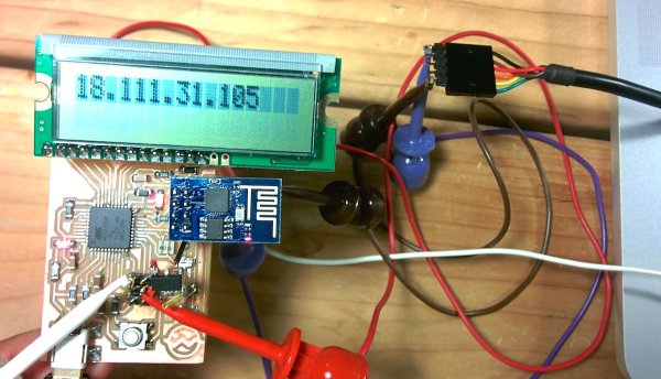
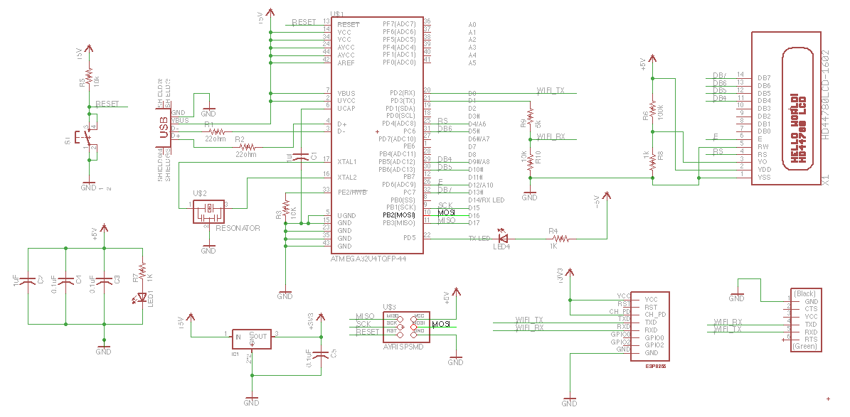
That’s the rough plan. I run the atmega32u4 and the LCD at 5V. The ESP8266 I power at 3.3V using a regulator. As for the logic chatter, I feed the 3.3V output of the ESP8266 to the atmega and I feed the output of the atmega through a voltage divider to bring it to 3.3V suitable for the ESP8266. This turned out to be a mistake that I will discover 15 hours later.
Mounting the lcd
I got a package from adafruits.com that I am modifying. First copy the package by
- opening target library
- selecting the device in the main window nav tree
- right-click copy to library
To get the mill to drill holes where needed, I am using the circle tool to draw filled cirlces (width 0).
ESP8266 package
I am making an eagle package and device for esp8266 header.
Steps:
- copy over a suitable part from another library (MA04-2 from con-lsb, a 4×2 header)
- open my library
- right click on part from source library
- click copy to library
- rename the package with
rename MA04-2.pac ESP8266_HDR_REVin the command bar - click package and select the package to edit
- get rid of all the crap that’s there (outline etc)
- add circles in the milling layer
- use name tool to give names (GND, RST, GPIO2, etc.)
- added some helpful text in the document layer
- create a new symbol (ESP8266)
- use pin tool to lay down 8 pins in row
- use name tool to add the same names I used in the package step
- create new device (ESP8266) (click device, pick a new name)
- use the place tool (plug thingie) to add the newly created symbol
- click new on the lower right to add the package
- click connect and go through and connect all the pins with all the pads
For more detail: Week 11: Networking with ESP8266