Summary of Wireless Energy Meter With Load Control
This project automates energy meter reading for multiple meters using Atmega16 microcontrollers and NRF24L01+ wireless modules. It eliminates manual data collection by transmitting pulse counts from three meters to a receiver, which calculates load and consumption. The system includes an alarm buzzer for excessive load and local data storage to prevent loss during connectivity issues.
Parts used in the Automated Energy Meter Reading System:
- Energy Meter (x3)
- NRF24L01 Wireless Module (x2)
- Atmega16 Microcontroller (x2)
- Optocoupler MCT2E (x3)
- Buzzer
- Linear Voltage Regulator (for 3.3V supply)
INTRODUCTION
Hi guys am a 3rd Year University Student of Lovely Professional University, India currently pursuing Electronics and Communication Engineering.
Youtube Channel :::: https://www.youtube.com/channel/UC6ck0xanIUl14Oor…
Facebook Profile :::: https://www.facebook.com/arnab.das.bwn
GitHub :::: https://www.facebook.com/arnab.das.bwn
WordPress :::: https://www.facebook.com/arnab.das.bwn
This Project is Based on Atmel’s Atmega16 Microcontroller as the main brain for computation.
NRF24L01+ Wireless communication module is used for the Wireless data transmission.
Today we have hundreds and thousands of Energy Meter installed in an Apartment Complex, Shopping Mall, School, University, Hostels and Lot more. The problem arises when meter is read by an employee to compute the bill per Energy Meter. Its require lot of manpower and cost.
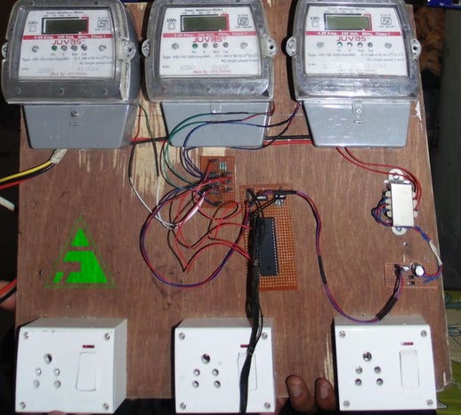
Here I have come up with a simple project that will save manpower and cost by automatically transmitting the Energy count of multiple Energy meter to the Host Or Service provider.
I have taken he data from Three Energy meter and transmitted the Data to the receiver, which computed the load and the the total consumption per meter.
If the load exceeds the permissible level then a buzzer starts.
Data gets saved in sender’s side so no data loss is produced if the receiver is switched off or connectivity is lost.
Here is the Working Video .
Different Components are:
- Energy Meter X 3
- NRF24L01 X 2
- Atmega16 X 2
- Optocoupler X 3
Step 1: Energy Meter Setup
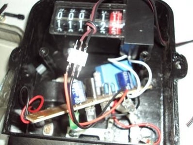
1. Open the Energy meter first.
2. Just Cut the Cathode terminal of the Cal LED.
3. Solder 2 wires on the 2 ends of the LED.
4. Connect the Cathode of the LED to the Pin1 of the Opto-coupler (MCT2E) and the other end of the LED to the Pin2 of the Opto-coupler.
5. Connect pin 4 of the opto-coupler to a Black wire and Pin5 to the brown wire. Connect the Black wire to the ground of the circuit board for the projects Prepaid energy meter or Auto meter reading projects. The Brown wire carry’s the pulse output.
6. Connect the power supply and load as per this picture.
Step 2: Basic Algo for Calculation
Here meter is interfaced with microcontroller through the pulse that is always blinked on the meter. Further that pulse is calculated as per its blinking period, using this principle we calculated it for one unit and accordingly what charge will be for a unit.
After 0.3125 watt energy uses Meter LED (calibrate) blinks. Means if we use 100 watt bulb for a minute then the pulse will blink 5.3 times in a minute. And this can be calculates using given formula.
Pulse= (Pulse rate of Meter* watt * 60) / (1000 * 3600)
If pulse rate of meter is 3200 imp and watt used is 100 then we have:
Pulse = (3200 * 100 * 60) / (1000 * 3600)
Pulse = 5.333333333 per minute
If 5.3333333333 pulses occurred in a minute then In one hour pulses will occur..
Pulse = 5.3333333333* 60 Pulse = ~320 ~320 Pulses will occur in a hour
So, in one hour 100 watt bulb consumed 100 watt electricity and almost 320 pulses blinks.
Now we can calculates one pulse electricity consumed in watt
One pulse (watt) = 100\320
One Pulse (watt) = 0.3125
Means 0.3125 watts electricity consumed a single pulse.
Now Units Unit = (one pulse energy (electricity) )* pulses / 1000
If One pulse = 0.3125 watt Pulses in 10 hours = 3200
Then Unit will be Unit = (0.3125 * 3200)/1000 Unit = 1 Means, One unit in 10 hours for a 100 watt bulb.
Now Suppose one unit rate is 7 rupee then For a single pulse cost will be
Single pulse cost = (7 * one pulse energy consumed) / 1000
Single pulse cost = (7 * 0.3125) / 1000
Single pulse cost = 0.0021875 Rupee
Step 3: Nrf24L01 (Credit to Http://gizmosnack.blogspot.in/)
The nRF24L01 module is an awesome RF module that works on the 2,4 GHz band and is perfect for wireless communication in a house because it will penetrate even thick concrete walls. The nRF24L01 does all the hard programming fore you, and even has a function to automatically check if the transmitted data is received at the other end. There are a couple of different versions of the nRF-family chips and they all seem to work in a similar way. I have for example used the nRF905 (433MHz) module with allmost the same code as I use on the nRF24L01 and the nRF24L01+ without any problems. These little modules has an impressive range, with some versions that manages up to 1000 m (free sight) communication and up to 2000 m with a biquad antenna.
nRF24L01 versus nRF24L01+
The (+) version is the new updated version of the chip and supports data rate of 1 Mbps, 2 Mbps and a “long distance mode” of 250 kbps which is very useful when you want to extend the broadcast length. The older nRF24L01 (which i have used in my previous posts) only support 1 Mbps or 2 Mbps data rate. Both the models are compatible with each other, as long as they are set to the same data rate. Since they both costs about the same (close to nothing) I would recommend you to buy the + version!
Part one – SetupConnection differencesThe nRF24L01 module has 10 connectors and the + version has 8. The difference is that the + version instead of having two 3,3 V and two GND, have its ground (the one with a white square around it) and 3,3 V supply, next to each other. If changing module from a new + version to an old one, make sure not to forget to move the GND cable to the right place, otherwise it will shorten out your circuit.
Here is a picture of the + version (top view), where you can see all the connections labeled. The old version has two GND connections at the very top instead of at the down right corner.
Power supply (GND & VCC)The module has to be powered with 3,3 V and cannot be powered by a 5 V power supply! Since it takes very little current I use a linear regulator to drop the voltage down to 3,3 V. To make things a little easier for us, the chip can handle 5 V on the i/O ports, which is nice since it would be a pain to regulate down all the i/O cables from the AVR chip. Chip Enable (CE)Is used when to either send the data (transmitter) or start receive data (receiver). The CE-pin is connected to any unused i/O port on the AVR and is set as output (set bit to one in the DDx register where x is the port letter). Atmega88: PB1, ATtiny26: PA0, ATtiny85: PB3SPI Chip Select (CSN)Also known as “Ship select not”.
The CSN-pin is also connected to any unused i/O port on the AVR and set to output. The CSN pin is held high at all the time except for when to send a SPI-command from the AVR to the nRF.Atmega88: PB2, ATtiny26: PA1, ATtiny85: PB4SPI Clock (SCK)This is the serial clock. The SCK connects to the SCK-pin on the AVR.Atmega88: PB5, ATtiny26: PB2, ATtiny85: PB2SPI Master output Slave input (MOSI or MO)This is the data line in the SPI system. If your AVR chip supports SPI-transfere like the Atmega88, this connects to MOSI on the AVR as well and is set as output. On AVR’s that lacks SPI, like the ATtiny26 and ATtiny85 they come with USI instead, and the datasheet it says:”The USI Three-wire mode is compliant to the Serial Peripheral Interface (SPI) mode 0 and 1, butdoes not have the slave select (SS) pin functionality.
However, this feature can be implementedin software if necessary” The “SS” refered to is the same as “CSN”And after some research i found this blog that helped me allot. To get the USI to SPI up and running I found out that I had to connect the MOSI pin from the nRF to the MISO pin on the AVR and set it as output. Atmega88: PB3, ATtiny26: PB1, ATtiny85: PB1SPI Master input Slave output (MISO or MI)This is the data line in the SPI system. If your AVR chip supports SPI-transfere like the Atmega88, this connects to MISO on the AVR and this one stays as an input. To get it working on the ATtiny26 and ATtiny85, i had to use USI as mentioned above. This only worked when I connected the MISO pin on the nRF to the MOSI pin on the AVR and set it as input and enable internal pullup.
Atmega88: PB4, ATtiny26: PB0, ATtiny85: PB0Interrupt Request (IRQ)The IRQ pin is not necessary, but a great way of knowing when something has happened to the nRF. You can for example tell the nRF to set set the IRQ high when a package is received, or when a successful transmission is completed. Very useful!If your AVR has more than 8 pins and an available interrupt-pin i would highly suggest you to connect the IRQ to that one and setup an interrupt request.Atmega88: PD2, ATtiny26: PB6, ATtiny85: –
Step 4: Basic Connection Diagram
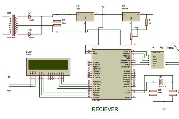
This Connection diagram is a schematic.
Step 5: Code
For CODE Visit GitHub https://github.com/arnabdasbwn
Source:
- How does the system calculate electricity consumption?
The system calculates consumption by measuring the blinking period of the meter LED pulses and applying specific formulas based on the pulse rate and wattage. - Can the nRF24L01 module be powered by 5 volts?
No, the module must be powered with 3.3 volts; however, its I/O ports can handle 5 volts safely. - What happens if the load exceeds the permissible level?
A buzzer starts sounding when the calculated load exceeds the predefined permissible limit. - Does the system lose data if the receiver is switched off?
No, data is saved on the sender's side, ensuring no data loss occurs if the receiver is off or connectivity is lost. - What is the difference between the nRF24L01 and nRF24L01+ versions?
The plus version supports higher data rates including long distance mode and has a different pin layout compared to the older version. - How many energy meters can this project monitor simultaneously?
The described project takes data from three energy meters and transmits it to a single receiver. - Which microcontroller is used as the main brain for computation?
Atmel's Atmega16 Microcontroller is used as the main brain for all computations in this project. - How is the meter interfaced with the microcontroller?
The meter is interfaced through an optocoupler that detects pulses generated by the calibration LED on the meter.