Summary of Work Progress
The author struggled with ESP32 debugging before switching to Atmega16u4 for a USB Profile project. Despite encountering milling difficulties due to thin traces and tool issues, they eventually moved to the more supported Atmega328p after failing to program the 16u4 in the Arduino IDE. The experience highlighted the importance of selecting microcontrollers with ample resources, compatible tools, and reliable fabrication options.
Parts used in the USB Profile Project:
- Atmega16u4 microcontroller
- Atmega328p microcontroller
- ESP32 networking chip
- Attiny44 microcontroller
- OpenOCD software
- Arduino IDE
- DFU Programmer
- 16 MHz external crystal
- 22 ohm resistor
- 22pF capacitors
I have been working on input and output devices communication for weeks. For those weeks, I spent so many times on the ESP32 debugging and got nothing solved, which makes me be so despair about the foreseeable failure of my final project. This wildcard week, however, saved my final project.
I joined the advanced embedded programming group and was hoping working on microcontrollers with larger storage for my final project and learning how to burn bootloader and programming different types of microcontrollers in this week.
On 4pm Thursday at CBA offices, we meet with Erik for a brief introduction about SAMD11 and OpenOCD, a free software on-chip debugging, in-system programming and boundary-scan testing tool for ARM systems. He gives a very solid tutorial and documentation about setting up OpenOCD in windows system with a downloaded binaries, programming/debugging with OpenOCD, burning an Arduino compatible bootloader with OpenOCD, and setup and programming with the Arduino IDE in the gitlab page.
As far as I understand, SAMD11 is an ARM controller. ARM is a family of RISC processor architectures. In particular, we’ll be looking at ARM Cortex-M processors, which are designed for microcontrollers. Unlike the 8 bit ATTINY chips we’ve been using, ARM microcontrollers are 32 bits. On average they also support faster clock rates and have more advanced peripherals. This means they can handle more demanding compute tasks, but also that they tend to have steeper learning curves. With the tools linked here you’ll be up to speed in no time. However, although being powerful, this microcontroller is also much harder to control. Because I have already run out of time, I do want to make sure my final project went smooth. Thus, instead of SAMD11, I found that the previous year is working on the USB Profile(with Atmega16u4).
There were several ways I can do to communicate my input devices and output devices.
- One is through networking chips like ESP32, which doesn’t work for me.
- Another is having two Attiny44 and connect the TX with the other’s RX and RX with TX.(Lara is doing this in his input and output weeks) A disadvantage of having two microcontrollers is that it become very tricky when programming. I think it is so good.
- The third option is to work with Atmega microcontrollers, burn bootloader, and program it.
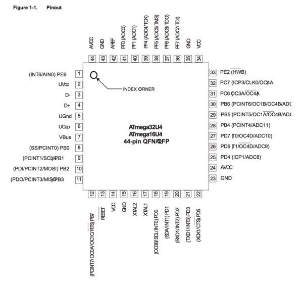
Thus, as suggested by Alex, I started with Atmega16u4. Compared with Atmega16u2, 16u4 has ADC and more pins. I didn’t use Atmega328p at the beginning is because I am a little bit refuse to use this chip that Arduino uses. However, compared with atmega328p. the resources and introduction for designing a board for 16u4 is very few. I only found one or two precedents with useful tutorials in the fab page who worked with this microcontroller.
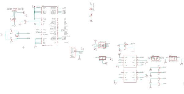
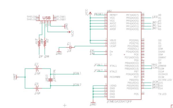
Schematic
 Basics
Some Notes to the schematic design for Atmega16u4(check the datasheet here)
- I made a mistake that I didn’t connect VCC WITH AVCC, GND with GND at the beginning, but they should always be connected.
- According to the datasheet, a 1uf capacitor should be connected to UCAP and GND
- As documented in Pietro Rustici’s page, the USB also needs 22ohm resistor in series on the datalines to limit the edge-speed of pulses and also to match the total impedance of the line.
- The DFU USB firmware comes pre-configured to work with 8 or 16 Mhz external Crystal.
- Each crystal needs two capacitors sized to match the crystal frequency in my case with the 16Mhz one i need two 22pF capacitors.
So basically in my schematic, everything on the left should be treated as default for a Atmega16u4 board.
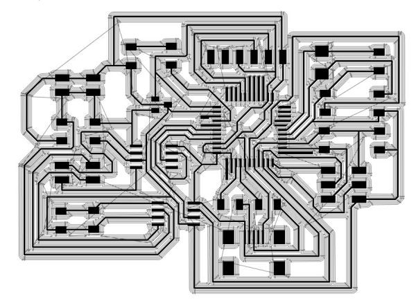
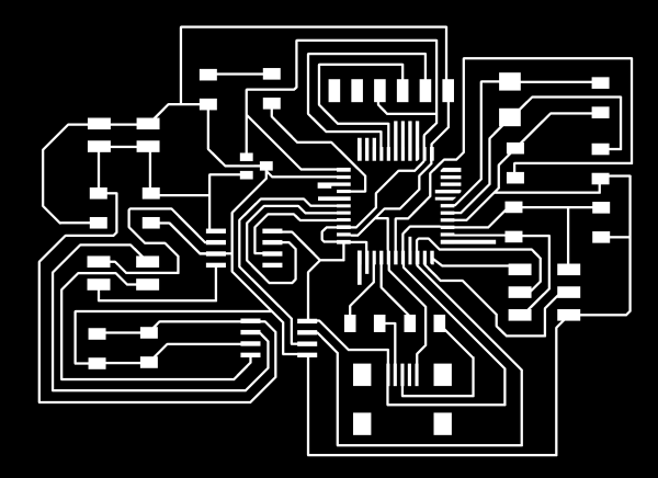
A huge mistake I have made for this board is that I didn’t notice in Andre Mao‘s documemtation, he did point out that the pin for the atmega16u4 is too thin and a 1/64’’ mill cannot go through. To change the pad size, here is a process cited from Shaoxiong Wang’s page.
Bad traces
- Open Library Manager
- Choose the library to modify and click Edit
- Double click the footprint that need to be modified
- Click Change -> SMD -> … to type in the desired size
- Click the pad to change (Or right-click the pad to change property)
If you having some difficulties of changing it to the correct size (mine just doesn’t change anything after all the steps), I suggested to edit the traces with illustrator. It is good that in illustrator, I am able to draw in pecision by typing numbers. In order to let the 1/64’’ go through, we need to draw at least 0.4mm black space between the white pin traces.
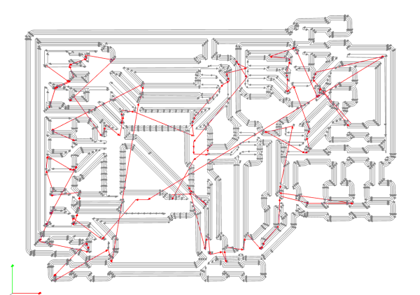
- A quick tip: I checked toolpath by layering the toolpath simulation with my board
But here comes another unexpected problem, I have done a lot of boards for this semester but I have never imagined I will be stucked at the mill phase.
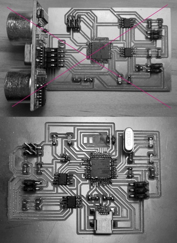
Because the traces are too thin, a lot of them are easy to be damaged and fly away and make my board become a trash then. The pin traces that haven’t been pulled out are so tiny and were always disappear when it comes out of the machine. After several failure, I went back to my trace and extend those pins to be longer.
My traces struggling.
However, the problem is not solved. The nightmare lasted for 2 days and I spent hours and hours on milling a board and I only got one usable board. It was Anthony pointed to me that I finally realized the problem is partially caused by the thin traces, but most likely because the three mills in our arch lab are bad and should be replaced.
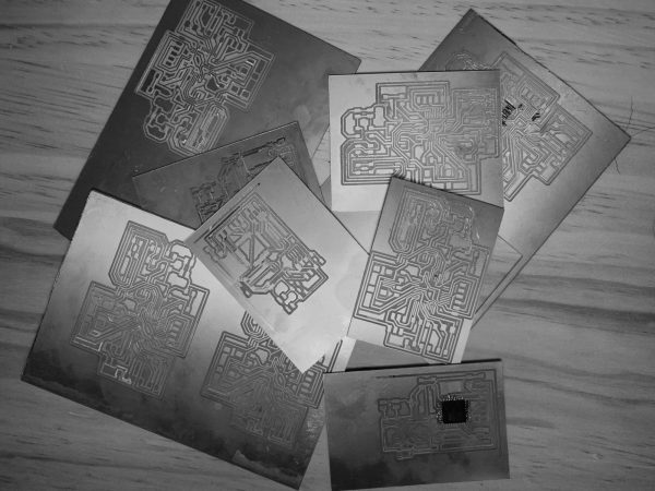
A big lesson: If the board edge is rough, it means the tool should be changed.
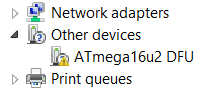
Another lesson comes soon. After I finally completed the board of atmega16u4 and it was detected by the computer with its USB port, but I found that I could not program it in Arduino. Th programming of Atmega16u4 only works with DFU Programmer. I do not have any foundation of C. In the command prompt, the only code I have been uploaded are examples given by Neil.
Anthony helped me search for a lot of solutions for programming the 16u4 in arduino. However, there is little resources about this microcontroller.
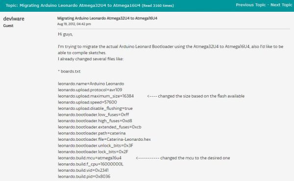
Although it is possible that you can use Arduino Leonardo, there will be a lot of problems happened because Leonardo is for 32u4, and it is very hard to migrate 16u4.
I programmed my board in the command prompt with the basic hello world script as the ending of using this chip and decided to work with a more promising microcontroller, Atmega328p.
This week is the most frustrating week for the semester, but I had some take-aways from those mistake I had made.
Before choosing a microcontroller, always to make sure it has enough storage, you can program it with your comfortable environment, and you are able to mill it with your tool.
We have a plenty of examples and tutorials about making a fabduino based on Atmega328p. There are also much resources about the microcontroller bugging online, which gave me much more confident.
It is better to work with a control board with its pins to be all pulled out and connected with smaller board than a large board that has more possibility of failure.
Schematic

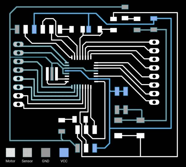
Board
Source: Work Progress
- Why did the author switch from SAMD11 to Atmega16u4?
The author chose Atmega16u4 because they ran out of time and needed a microcontroller that worked smoothly for their final project. - What are the advantages of ARM microcontrollers like SAMD11 over ATTINY chips?
ARM microcontrollers are 32 bits, support faster clock rates, have more advanced peripherals, and can handle more demanding compute tasks. - Why was the Atmega328p initially avoided by the author?
The author refused to use the Atmega328p at first because it is the standard chip used by Arduino. - What specific mistake was made regarding the VCC and AVCC connections in the schematic?
The author initially failed to connect VCC with AVCC and GND with GND, which must always be connected. - What component is required on the datalines to limit edge-speed and match impedance?
A 22ohm resistor needs to be placed in series on the datalines. - Why did the milling process fail repeatedly for the Atmega16u4 board?
The failure was caused by traces being too thin to survive the milling process and bad mills in the arch lab that needed replacement. - What programming method is required for the Atmega16u4 instead of the Arduino IDE?
The Atmega16u4 requires a DFU Programmer for programming. - What lesson was learned about choosing a control board layout?
It is better to work with a control board where all pins are pulled out and connected with a smaller board rather than a large board prone to failure.