Summary of XOD-powered Rechargeable Solar Lamp
This article details a high-performance, off-grid solar lamp using two ATTiny85 microcontrollers and XOD graphical programming. Unlike cheap commercial lamps, this design employs fuzzy logic for Maximum Power Point Tracking (MPPT) and adaptive LED dimming based on battery status. The system separates sensing and control tasks between two chips to optimize energy harvesting and extend illumination time efficiently while remaining cost-effective to build.
Parts used in the XOD-powered Rechargeable Solar Lamp:
- Arduino IDE with ATTinyCore extension
- Sparkfun USBTinyISP ATTiny programmer
- Pololu adjustable low-voltage boost converter (U1V11A)
- High power white or RGB LED with heatsink
- Microchip ATTiny85 in 8-pin DIP package (x2)
- 8 pin DIP IC sockets (x2)
- Bulk storage capacitor (16v 220 uF)
- Output capacitor (6.3v 47uF)
- Current-limiting resistors (50 ohm 1/4 watt)
- i2c pull-up resistors (4.7k, x2)
- Panel voltage sense divider resistors (100k, 470k)
- Current sense resistor (10 ohm 1/2 watt 1% tolerance)
- Bypass capacitors (0.1uF ceramic, x2)
- Lithium-ion rechargeable batteries (3.7v 100mAh, x2)
- Barrel plug input jack
- Mini terminal blocks and solder-pad board
There are inexpensive solar garden/walkway lamps available at most home goods and hardware stores. But as the old saying goes, you usually get what you pay for. The usual charging and illumination circuits they use are simple and cheap, but the light output you get is anything but impressive (and barely enough for anyone using your walkway to see where they’re going!)

This is my attempt at designing an off-grid lighting module that’s a significant improvement, while still being relatively inexpensive to make. By giving it some “brains.” XOD.io is a new IDE compatible with the Arduino embedded development platform, where you can “write” code graphically. The environment transpiles your graphical sketch to modern C++, which is remarkably efficient at generating compact code, and generates source fully compatible with the stock Arduino IDE without requiring further external dependencies. That way even small, inexpensive microcontrollers with limited program and data storage resources can be employed to take on complex tasks.
This project shows how two Arduino-compatible ATTiny85 microcontrollers working together can be used to manage the power requirements of the lamp. The first processor handles sensing environment data from the external hardware, and the second tries to harvest the most energy from the sun it can during the day, and then control the illumination of a high-power LED as a storage battery discharges at night. The second processor accomplishes its job via a compact implementation of “fuzzy logic” control. The software for both chips was developed exclusively within the XOD environment.
Step 1: Required Materials
- Arduino IDE, latest version, with ATTinyCore extension installed from the “Boards” manager
- Sparkfun USBTinyISP ATTiny programmer, 11801 or equivalent Sparkfun product page
- Pololu adjustable low-voltage boost converter with shutdown input, U1V11A or equivalent Pololu product page
- High power white or RGB LED with heatsink, common anode, Adafruit 2524 or equivalent Adafruit product page
- Microchip ATTiny85 in 8-pin DIP package, 2 Mouser product page
- 8 pin DIP IC sockets, 2
- Bulk storage capacitor, 16 v 220 uF
- Output capacitor, 6.3v 47uF
- Current-limiting resistors, 50 ohm 1/4 watt
- i2c pull-up resistors, 4.7k, 2
- Panel voltage sense divider resistors, 1/4 watt, 100k, 470k
- Current sense resistor, 10 ohm 1⁄2 watt 1% tolerance
- Bypass capacitors, 0.1uF ceramic, 2
- 2 3.7 v 100mAh lithium-ion rechargable battery, PKCELL LP401 or equivalent
- Barrel plug input jack for panel, 1
- Mini terminal blocks 3”x3” solder-pad board, and thin solid-core wire for making connections
- An oscilloscope, multimeter, and bench power supply will almost certainly be required for testing
Step 2: Environment Setup
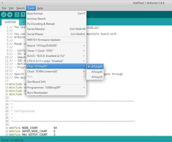
The XOD environment doesn’t support the ATTiny series of processors out of the box, but using a couple third-party libraries from the Arduino universe it’s straightforward to add support for this series of AVRs. The first step is to install the “ATTinyCore” library from the Arduino IDE’s “Tools → Board → Board Manager” dropdown menu. Ensure that the settings as shown in the included image are correct – remember that you have to hit “Burn bootloader” to change the brownout voltage and clock speed setting fuses before uploading any code!
The source code for this library is available at: https://github.com/SpenceKonde/ATTinyCore
Another helpful library to have from the repository is “FixedPoints”, which is a compile-time implementation of fixed point math for Arduino-supported processors. The ATTiny has limited SRAM and program memory, and it helps a lot with shrinking the final sketch size to use a 2 byte integer for general data storage, rather than a floating point type, which requires 4 bytes on the AVR. Execution speed should also be improved as the ATTiny doesn’t have a hardware-multiplication unit, much less hardware floating point!
Source code is available at: https://github.com/Pharap/FixedPointsArduino
The tutorial on how to create, transpile, and deploy XOD graphical sketches at: https://github.com/Pharap/FixedPointsArduino will help a lot with understanding how the included source files were created.
Step 3: Design Overview
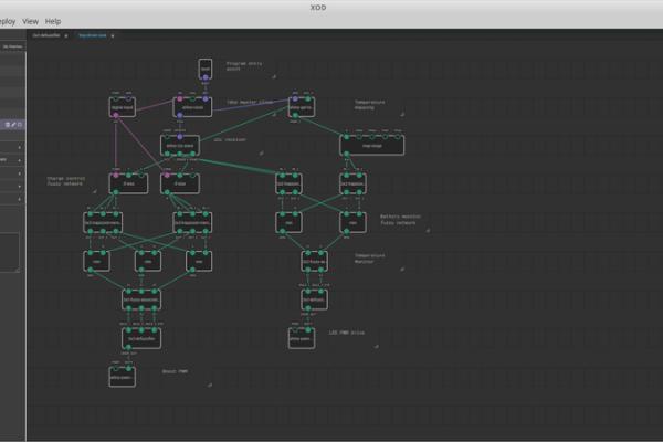
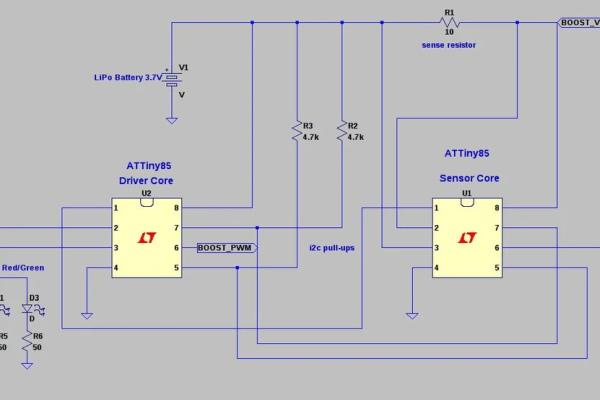
On the board two ATTiny85 processors are connected via an i2c interface, and are used working together to manage sensing the voltage of the solar panel, current flowing into the battery from the boost converter while the panel is illuminated, the battery voltage, and the battery temperature.
The boost converter is an off-the-shelf module based on a Texas Instruments TPS6120 IC, which can take an input voltage as low as 0.5 volts and boost it to anywhere from 2 volts to 5 volts. The sensor core comprises several functional blocks. The master clock starts running as soon as power is applied to the boost converter from solar panel input. This starts the sketch executing, and the first thing is to determine whether the panel is illuminated enough to provide charging current to the battery.
The solar panel voltage is passed though two digital filters, and if it’s above a certain threshold the system determines that the panel is illuminated and gates the master clock into the current-sense monitor. This is a analog to digital converter channel of the chip, configured differentially, which senses the voltage across a 10 ohm 1% tolerance resistor connected in series between the boost converter’s output and the battery input. When the panel isn’t illuminated this ATTiny sends a signal to the second ATTiny telling it to monitor LED power instead of charging power, and turn the boost converter off and isolate the input so the battery doesn’t send current back out through the panel.
The second ATTiny core is where the LED controller and battery charge monitoring system executes. Panel voltage, battery voltage, and battery charging current data is sent to this core for processing through a fuzzy-logic network, which attempts to generate an appropriate PWM signal to apply to the SHTDN pin, thereby controlling the amount of current sent to the battery to charge it when illuminated – a basic form of maximum power-point tracking (MPPT.) It also receives a signal from the sensor core telling it whether it should turn the LED on or off, depending on the output of the sensor core’s day/night flip flop.
When the LED is active at night this ATTiny monitors the battery voltage data sent to it from its buddy, and its own on-chip temperature sensor, to get a rough estimate on how much power is being pushed into the LED (the battery voltage decreases and chip temperature increases with current drawn out of its pins.) The fuzzy-logic network associated with the LED PWM patch attempts to make a judgement on how much battery power is still available, and decrease the LED intensity as the battery is depleted.
Step 4: Creating Custom Patches From the XOD Core Library
Several custom patch nodes were used for this design, some of which can be easily constructed entirely from included XOD nodes, and some which were implemented in C++.
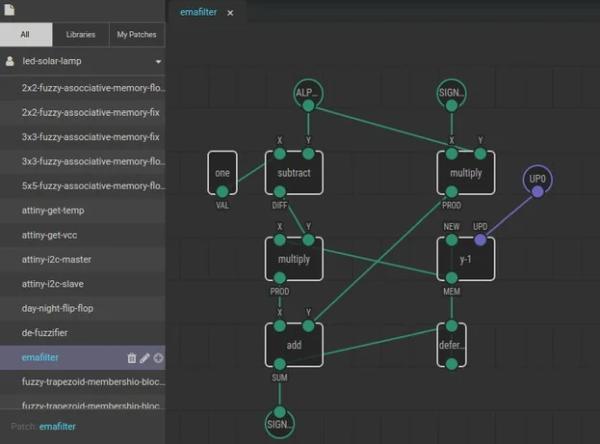
The first of the two custom patch nodes in the pictures an implementation of an exponential moving-average filter. This is a low-overhead low-pass digital filter used in series in the sketch, once to filter the incoming solar panel voltage for the logic core, and once more to feed the trigger which determines long-term ambient illumination. See the Wikipedia entry on exponential smoothing.
The node structure in the image is just a direct graphical representation of the transfer function in the article, connected together using links from the appropriate inputs to outputs. There’s a defer node from the library which allows a feedback loop to be created (XOD will warn you if you create a feedback loop without inserting a delay in the loop, as described in the XOD execution model.) With that detail taken care of the patch works well, it’s that’s simple.
The second custom patch node is a variation on the stock flip-flop included with XOD, that is fed with the filtered panel voltage. It latches high or low depending on whether the input signal is above or below a certain threshold. Cast nodes are used to convert Boolean output values to the pulse data type to trigger the flip flop, as the state transitions from low to high. The design of this patch node should hopefully be somewhat self-explanatory from the screenshot.
Step 5: Creating Custom Patches Using C++
For special requirements where the node functionality needed would be too complex to easily depict graphically, or which rely on Arduino libraries not native to the stock Arduino environment, XOD makes it easy for those with some C/C++ knowledge to write bite-size chunks of code that can then be integrated into a patch the same as any other user-created or stock node. Selecting “create a new patch” from the file menu creates a blank sheet to work with, and input and output nodes can be dragged in from the core library’s “nodes” section. Then the “not-implemented-in-xod” node can be dragged in, and when clicked it will bring up a text editor where the required functionality can be implemented in C++. How to handle internal state and accessing the input and output ports from C++ code is covered here.
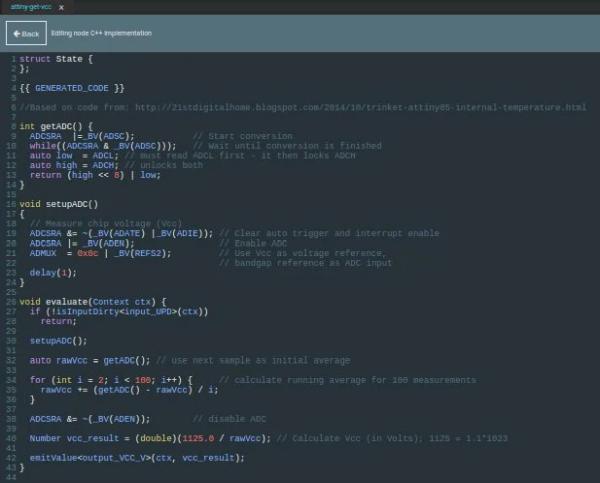
As an example of implementing custom patches in C++, two further custom patches for the driver core are used for putting out an estimate of the driver core’s supply voltage and core temperature. Along with its fuzzy network this allows a rough estimate of the remaining battery power available to power the LEDs when it’s dark.
The temperature sensor patch is also fed with the output of the supply voltage sensor to obtain a better estimate – sensing core temperature allows us to obtain a rough estimate of how much power is being burned in the LEDs, and combined with the supply voltage reading when running off the battery a further rough estimate of how much battery power is remaining. It doesn’t have to be super-accurate; if the core “knows” that the LEDs are drawing a lot of current but the battery voltage is rapidly falling it’s probably safe to say that battery power is not going to last very much longer, and it’s time to shut the lamp down.
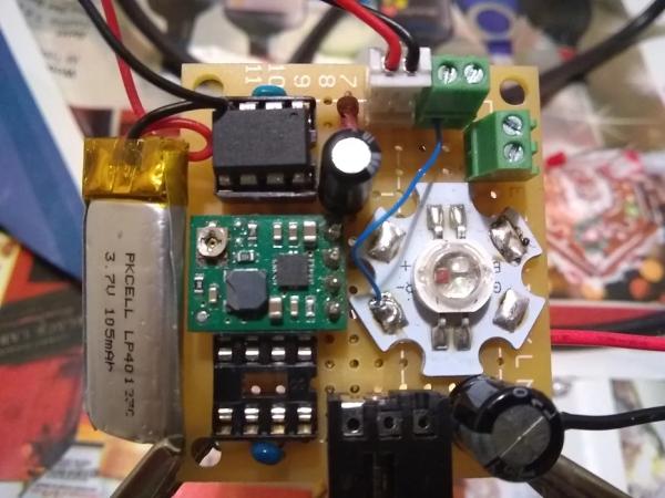
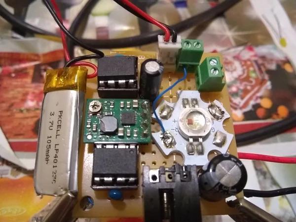
Step 6: Construction
I built the project on a small piece of prototyping board with copper pads for through-hole parts. Using sockets for the ICs helps a lot for programming/modification/testing; the USBTiny ISP from Sparkfun has a similar socket on its board so programming the two chips just consists of plugging the programmer into a PC USB port, uploading the transpiled XOD code from the included Arduino .ino files with the appropriate board and programmer settings, and then gently removing the chips from the programmer socket and inserting them into the protoboard sockets.
The Pololu TPS6120 based boost converter module comes on a riser board soldered into the protoboard on pin headers, so it’s possible to save space by mounting some components underneath. On my prototype I put the two 4.7k pullup resistors underneath. These are required for the i2c bus between the chips to operate correctly – communication won’t work right without them! On the right hand side of the board is the input jack for the solar panel’s plug and the input storage capacitor. It’s best to try to connect the jack and this cap directly together via “runs” of solder, not hookup wire, to get as low resistance a path as possible. Runs of solid solder are then used to connect the positive terminal of the storage capacitor directly to the input voltage terminal of the boost module, and the boost module’s ground pin directly to the jack’s ground pin.
To the right and left of the sockets for the two ATTinys are 0.1uF despike/deglitching capacitors. These components are also important not to leave out, and should be connected to the ICs power and ground pins through as short and direct a path as possible. The 10 ohm current sense resistor is at the left, this is connected in line with the output from the boost converter and each side is connected to a sensor core input pin – these pins are set up to work as a differential ADC to indirectly measure the current into the battery. Connections between IC pins for the i2c bus and to the boost converter shutdown pin, etc. can be made using hookup wire on the underside of the protoboard, very thin solid-core hookup wire works great for this. It makes changes easier and also looks a lot neater than running jumpers between holes on the top.
The LED module I used was a tri-color RGB unit, my plan was to have all three LEDs active to produce white when the battery was nearly fully charged, and slowly fade the blue LED out into yellow as charge was depleted. But this feature has yet to be implemented. A single white LED with one current-limiting resistor will work OK, too.
Step 7: Testing, Part 1
After programming both ATTiny ICs with the included sketch files via the USB programmer from the Arduino environment it helps to test that the two cores on the prototype are functioning properly prior to trying to charge the battery off the solar panel. Ideally this requires a basic oscillscope, multimeter, and bench power supply.
The first thing to check is that there are no short circuits anywhere on the board prior to plugging in the ICs, battery, and panel into their sockets to avoid possible damage! The easiest way to do this is to use a bench power supply that can limit its output current to a safe value in case of that situation. I used my bench supply set at 3 volts and 100 mA limit connected to the solar panel input jack terminals to the positive and negative power supply leads. With nothing other than the passive components installed, there should be essentially no current draw registered on the power supply’s current monitor to speak of. If there’s significant current flow, or the supply goes into current-limiting, something has gone wrong and the board should be checked to make sure there are no miswired connections or capacitors with reversed polarity.
The next step is to ensure the boost converter is working correctly. There’s a screw-potentiometer on the board, with the power supply still connected and four of the converter’s pins connected approprately the potentiometer should be turned with a small screwdriver tip until the voltage at the output terminal of the module reads around 3.8 to 3.9 volts. This DC value won’t change during operation, the driver core will control the average output voltage via pulsing the module’s shutdown pin.
Step 8: Testing, Part 2
Next thing to check is that i2c communicaton is working OK, with the board running off bench power the sensor core IC can be installed. On an oscilloscope there should be pulsing signals on both pin 5 and pin 7 of the physical chip, this i2c driver on the chip attempting to send data to its buddy. After shutting down the driver core can be installed and the connection checked with an oscilloscope again, there should be a larger sequence of pulses visibile on both lines. This means that the chips are communicating correctly.
It helps to have the battery slightly charged for the final full test. The bench supply can also be used to accomplish this, with the current limit set to about 50 mA and the voltage still at 3.8 volts, leaving the LiPo battery connected directly for a few minutes.
The final step is to test out the full system – with everything connected up if the panel is covered for ten or 15 seconds the light should come on being driven via the driver core’s PWM output. With the panel in bright sunlight, the battery should charge from the boost converter’s output. The fuzzy logic network can be indirectly inspected to see if it’s working correctly by looking at the PWM line driving the boost converter’s shutdown pin; as illumination increases with battery with low state of charge the pulse width should increase, showing that as more power becomes available from sunlight, the driver core is signalling that more power shoud be sent into the battery!
Step 9: Appendix on Fuzzy Logic
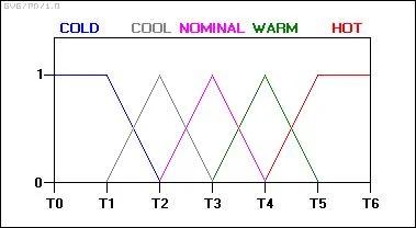
Fuzzy logic is a machine learning technique that can be used in the control of hardware systems wherethere’s uncertainty in many of the parameters of the system being controlled, making an explicit input to output control solution for the goal hard to write down mathematically. This is accomplished by using logical values that fall somewhere between 0 (false) and 1 (true), expressing uncertainty in a value more like the way a human would (“mostly true” or “not really true”) and allowing a a grey area between statements which are 100% true and 100% false. The way this is accomplished is through first taking samples of the input variables on which a decision needs to be based on and “fuzzifying” them.
The heart of any fuzzy logic system is a “fuzzy associative memory.” This is reminiscent of a matrix, where in the case of the battery charging circuit a 3×3 set of values ranging between 0 and 1 is stored. The values in the matrix can be roughly associated with how a human would reason about what the PWM factor controlling the SHTDN pin of the boost converter should be, depending on how the membership function above qualifies a given set of inputs. For example if the panel input voltage is high, but the current being drawn into the battery is low, it probably means that more power can be drawn and the PWM setting is not optimal and should be increased. Conversely, if the panel voltage goes low but the charger is still attempting to push a large current into the battery power will also be wasted, so it would be best to decrease the PWM signal to the boost converter. Once the input signals are “fuzzified” into an fuzzy set, they’re multiplied by these values, similar to the way a vector is multiplied by a matrix, to generate a transformed set which is representative of how heavily the “knowledge” contained cell of the matrix should be factored into the final combination function.
Using the “not-implemented-in-xod” node which allows XOD nodes that implement custom functionality too complicated to be reasonable to make from the stock building blocks, and a little Arduino-style C++, the associative memory, weighting function, and “fuzzifier” similar to the blocks described in this reference: http://www.drdobbs.com/cpp/fuzzy-logic-in-c/184408940 are straightforward to make, and much easier to experiment with.
- How does the system manage power requirements?
Two ATTiny85 microcontrollers work together via an i2c interface to handle sensing and energy management. - What software environment is used to develop the code?
The project uses XOD.io, a graphical IDE that transpiles sketches to efficient C++ compatible with the Arduino IDE. - Can the system operate without external dependencies?
Yes, the generated source code is fully compatible with the stock Arduino IDE without requiring further external dependencies. - How does the controller determine if the panel is illuminated?
The system passes solar panel voltage through digital filters to check if it exceeds a specific threshold. - What technique is used for maximum power point tracking?
A compact implementation of fuzzy logic control generates appropriate PWM signals to optimize charging current. - How does the lamp adjust brightness at night?
The driver core monitors battery voltage and chip temperature to decrease LED intensity as the battery depletes. - Why are two 4.7k pull-up resistors required?
These resistors are necessary for the i2c bus between the two chips to operate correctly. - What testing equipment is recommended for verification?
An oscilloscope, multimeter, and bench power supply are almost certainly required for proper testing.