Downloads
Download the Download FreePC files in and the detector board layout png file in zipped forma: schottkydedtector080309
Find updates at www.projects.cappels.org
Starting to do a little work at 330 MHz, I decided that my existing field strength meters were not adequate for for my needs. The 330 MHz project came to a stop, and I set out to put together a field strength meter with a moving needle indicator, with higher sensitivity than the others I have built, and the ability to indicate RF in the 2.4 GHz band.
Before getting too far into the description, I would like to apologize to those who design real field strength meters and acknowledge that this is device indicates relative field strength from moment to moment. It is not calibrated and I have certainly not gone to any pains to assure a flat frequency response, or even a characterized frequency response for the detector. Having said that, this is a pretty sensitive indicator, and there are provision to add a tuned circuit to the input so as to give the device some selectivity. I will continue to make loose use of the term “field strength meter” in this web page to aid web searches for this kind of instrument. Such are the conditions of our time. I kindly request the reader’s kind indulgence in this matter.
Overview
External Connections and controls
When an antenna is attached, (or even if not, in the presence of a strong RF field) the field strength meter has a moving coil meter to indicate relative field strength. The box holds a Schottky diode detector, a DC amplifier, and a meter display. If the parts used in construction are the same values shown in the schematic, the meter shows full scale (“+3db” on the surplus store VU meter movement) when the output of the Schottky diode detector is between 1.6 millivolts and 160 millivolts, depending up the setting of the gain control. Since opamps are used as amplifiers, the range of the gain control can be modified easily. The actual sensitivity in terms of field strength is primarily a function of the antenna system, and that is well beyond the scope of this web page.
An RCA connector with which you can attach an antenna (as in the photograph near the top of the page), of if desired signal preconditioning circuits such as a filter and/or preamp. I expect that for most of my low power uses, a short whip antenna or no antenna at all will be sufficient.
A stereo headphone jack that provides a way to connect the amplified detector output to a digital voltmeter, chart recorder, oscilloscope, or other instrument, and also allows the application of an offset voltage from an external device. I had imagined adding an external logger with an automatic offset adjust function.
An offset knob allows correction for drift in the Schottky detector as well as offsets created by interfering signals. A coarse offset control on the circuit board allows for compensation for the mismatch between components.
A power switch and pilot light complete the set of user controls.
The meter operates from the power of two AA cells. With new Zinc Chloride cells installed, it draws only about 3 milliamps, including the LED when the meter reads full scale, and about 3.5 milliamps when the meter reads zero, so it seems that the use of an external power supply would not be worthwhile.
The Circuit
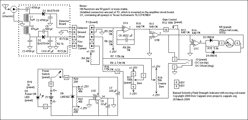
The field strength meter is a broad band temperature compensated biased Schottky diode detector with an offset adjustment, followed by a buffer (U1A), amplified by a single gain block (U1B), which drives the meter driver (U1C). A integrated circuit voltage reference is used to generate stable +1.25 and -1.25 volt reference supplies and an opamp (U1D) provides a ground reference which is at half the voltage of the 3 volt battery. The circuit blocks will be discussed in turn below.
Temperature Compensated Biased Schottky Diode Detector
The detector board takes its input from short wires soldered directly to an RCA audio connector.
The Schottky diode detector is built on a single sided fiberglass circuit board that is separate from the amplifier board. This was mainly because the detector board needed to be close to the RCA input connector, which would be on the front panel. With the presence of the other connector and the controls on the front panel, there was no room for a larger circuit board to accommodate the DC amplifier.
Whip antennae require a ground structure in order to work. The large copper areas on the detector board, as show in the picture above, are intended to improve the efficiency of a short whip antenna at GHz frequencies. Being in a mostly unshielded enclosure, the meter can detect strong GHz range signals picked up on its internal leads, without the need for an external antenna.
Advantages of using a printed circuit board for the detector over using other construction methods, are that it allows the use of surface mount parts, which not only provides for small physical dimensions which minimize parasitic reactances, but also provide for good thermal coupling of both of the diodes to the circuit board. Keeping the diodes at the same temperature is important in keeping temperature caused drift as small as possible.
For more detail: A Field Strength Meter Using A Biased Schottky Detector using microcontroller


