Part 1: Introduction
For some people, interrupts are a mystical thing that they think they will never understand. To that I say non-sense! And to that effect and to help us also better understand VGA, let’s see if we can’t output some basic VGA signals like we’ve done before, but this time using some interrupts!
In this article we’ll explore how to output VGA signals from an Arduino UNO by using the timer interrupt to keep output in sync with the exact timing required by the VGA protocol. The end result will be a very empty ‘main’ loop in our software and a lot of interrupt code that handles everything else. The Arduino is only running at 16 MHz so doing VGA with interrupts on it is really pushing the limits!
Arduino VGA via Interrupts – Project Setup
Purpose & Overview Of This Project
The purpose of this project is to output VGA signals @ 800×600 resolution in a similar fashion as we’ve done in past Arduino VGA articles. Tri-color output blue, green and red. While this seems boring to average joe-schmoe jack, getting a reliable and static output to a VGA monitor is the first step to actually being able to output more advanced signals and graphics. The timer interrupt in the Arduino will be used to tell the microcontroller everytime a VGA Hsync is necessary.
For this project we’ll use the Arduino UNO platform for the processing and a small VGA breakout board that I built back in the day for the masochist’s video card. Everything else for this project will be theory and software which means not much hardware to connect together but a lot of software to understand and figure out in order to match the VGA protocol.
Part 2: Parts List
Arduino UNO
VGA Breakout Board
Jumper Wire
VGA Computer Monitor
+9v Battery Connector
Battery Holder
Parts List Details
The parts used in this project are all listed out above, but the more interesting and necessary parts are listed out below with a little more detail to describe their function.
Arduino UNO
The Arduino UNO will be the microcontroller doing all the work for this project. Understanding our code and executing it so that the proper VGA signals that we want are output to the monitor without any huge issues.
VGA Breakout Board
This breakout board was originally designed to help the Masochist’s Video Card project connect easily to a monitor but as I’ve written more and more articles about VGA related topics I find that it has become extremely useful.
Jumper Wire
Standard jumper wire, nothing special. We’ll use it to connect the arduino to VGA monitor. Alternatively you could use jumper cables or aligator clips.
Part 3: Schematic
Schematic Overview
This is one of those times when the schematic for the project is super simple because most of the work is being done in software. So below you can see the few connections necessary for the harware side of this project.
Schematic Specifics
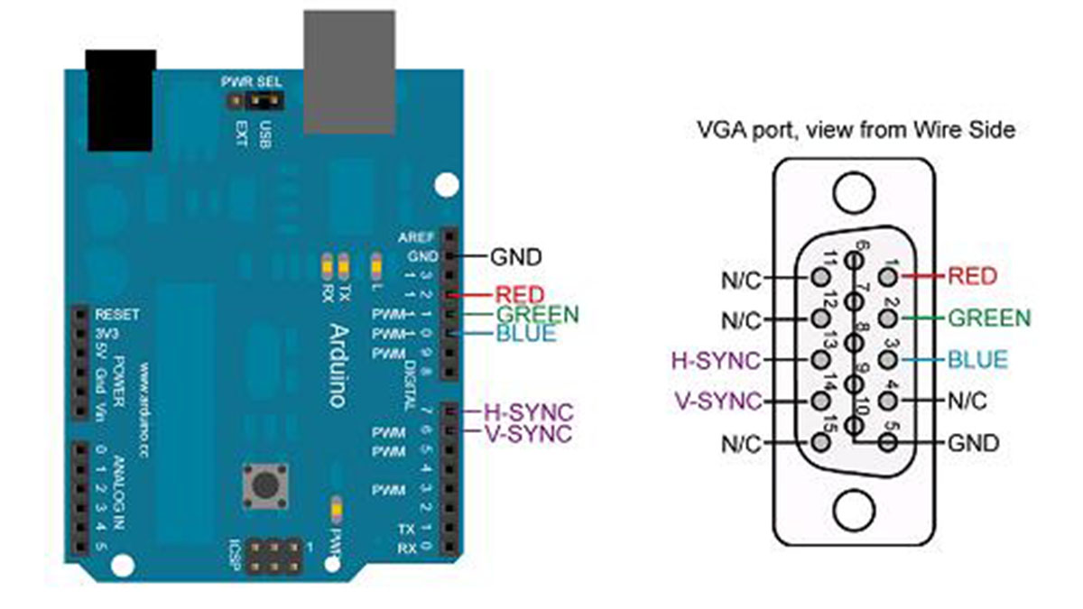
RGB Connections
VGA uses red green and blue to mix together and create all the colors of the rainbow. Setting any of these pins will tell the monitor how intense the specific color should shine. For what we’re doing we won’t even get into color intensities, everything will be 100% red, 100% green or 100% blue.
Hsync and Vsync Connections
In order to know what line you’re currently outputting data for and if the frame of data is complete, two synchronization signals are used: Horizontal Sync and Vertical Sync. These are the most important signals, if the timing is wrong on these guys, the VGA output won’t work at all.
Ground Connections
There are many grounds on the VGA connector for designers who want to go the extra mile and make a professional VGA controller. However, for what we’re doing you only need to connect ground to PIN 5. That’s it!
Part 4: Theory of Operation
Basic VGA Theory
The theory of VGA relies upon being able to successfully display the color data. Then horizontal synchronize and vertical synchronize, all at specific times that cannot be missed.
The Arduino UNO runs off of a 16 MHz crystal oscillator and since it runs 1 clock cycle per instruction that means that each executed assembly instruction of our program will take exactly (1 / 16,000,000) of a second or about 62.5 nanoseconds.
Using Interrupts

Since the most common synchronization pulse is the horizontal sync, we’ll set up a timer interrupt to trigger interrupt every 3.2uS. This means we’ll use the interrupt itsself to display all video data and handle Vsync then return to the main loop and 3.2uS later, the interrupt will trigger again repeat outputting the line data.
Since the timer interrupt will be set to interrupt every 3.2uS that means the main loop will only have time to execute about 48 assembly instructions. Since we’re programming entirely in C, that doesn’t give us a lot of time to do much in the main loop. However, it is just enough time to set what color should be output on the screen, so we should still be able to reach our stated goal.
For more detail: Arduino VGA via Interrupts using AVR Microcontroller