We all know that one of the places where power wastage happens most in homes and offices is at staircases. We usually turn on light at stairs and leave it in a hurry. In this project we are going to design a stair case lamp which works on battery and only turn on the lights only when someone is present at there. This circuit can be used to save power and it can be used as an emergency backup light.
The circuit works on two conditions – one is presence of light in its location and second is presence of human being, only when these two conditions are met, the controller turns the backup light ON.
These two conditions are tested by two sensors one is LDR and other is Motion sensor module. The LDR senses the presence of light and Motion sensor detects the presence of a human being in its range.
The image on the left side shows the sensor LDR (Light Dependent Resistor) and the picture on the right side show the PIR Sensor or Motion Sensor Module. PIR Sensor is basically an IR (Infrared Receiver). It consists of sensitive IR receives which detects the IR (Infra Red) rays in its region.We know that every living organism emits IR rays and so the human body. Whenever a there is a human in the sensor module region it detects the presence of IR rays.
Whenever a human present in the sensing region of module, the sensor picks up IR changes as human body emits IR rays, so now these changes of IR picked up by module are filtered by electronics in the module and as of signaling the changes in IR, A pulse is generated by the module. This pulse is of duration 5sec by default.
So whenever a human crosses the sensing region of module, it generates a pulse of 5 sec. So presence of human is detected by IR rays by this module.
The motion sensor module will have two pots or presets one of them is to adjust the sensing region of the module and the second is for varying the time of high pulse output on detection of motion. The duration of pulse can be adjusted from few second to few minutes. You can understand more about it by this PIR sensor circuit.
The LDR in this circuit works as a variable resistor. The resistor of the LDR changes based on the light intensity. When the light falling on the LDR is low the resistance of the LDR will be high. When the light falling on LDR is high the resistance across terminals of LDR will be very low compared to low light resistance.
Components Required
Hardware:
ATMEGA32
Power supply (5v),
AVR-ISP PROGRAMMER
100uF capacitor
LED
220Ω, 1KΩ resistors
LDR(Light Dependent Resistor)
100KΩ pot or preset,
Any motion sensor module (HC-SR501)
2WATT LED
TIP122 transistor.
Software:
Atmel studio 6.1
Progisp or flash magic
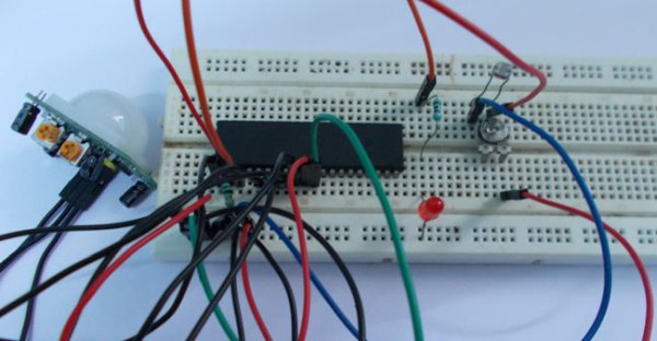
Circuit Diagram and Working Explanation
As shown in the above automatic staircase lighting circuit, there is no need to connect an external crystal here. Because the ATMEGA works on internal 1MHz, Resistor-Capacitor oscillator on default. Only when the accuracy of clock is needed, as application of high precision counting, external crystal is attaches. When the controller is first bought, it is fused to work on internal crystal by default.
For more detail: Automatic Staircase Light