Summary of Microcontroller Based Electronic Voting Machine
This project builds a simple four-candidate electronic voting machine using an ATmega32A microcontroller. Four pushbuttons register votes, which the microcontroller tallies and displays per candidate on a 16x2 LCD. The design uses PORTA for the LCD data lines, two LCD control lines (RS and E), disabled JTAG if PORTC is reused, and common capacitors, resistors, and a 5V supply. Programming is done with Atmel Studio and an AVR ISP tool.
Parts used in the Electronic Voting Machine:
- ATmega32 (ATMEGA32A) microcontroller
- Power supply (5V)
- AVR-ISP programmer
- JHD_162A 16x2 LCD (or equivalent)
- 100nF capacitor (five pieces)
- 100uF capacitor (across power supply)
- Pushbutton switches (five pieces)
- 10KΩ resistors (five pieces)
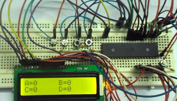
Whenever we go to vote for elections we come to see electronic voting machines. In this project we are going to design and develop a simple voting machine by using ATmega32A microcontroller. Although we can use the controller to get more than 32 people voting machine, to keep everything simple we are going to make a voting machine for a size of four people.We will have four buttons for four people and whenever a button is pressed, a vote goes for the corresponding person and the number of votes each person gets shown on LCD.
Components Required
Hardware:
ATMEGA32
Power supply (5v)
AVR-ISP PROGRAMMER
JHD_162ALCD (16×2 LCD)
100nF capacitor (five pieces), 100uF capacitor (connected across power supply)
button(five pieces),
10KΩ resistor (five pieces).
Software:
Atmel studio 6.1
progisp or flash magic.
Circuit Diagram and Working Explanation

As shown in the above electronic voting machine circuit, PORTA of ATMEGA32 microcontroller is connected to data port LCD. Here one should remember to disable the JTAG communication in PORTC of ATMEGA by changing the fuse bytes, if one wants to use the PORTC as a normal communication port. In 16×2 LCD, there are 16 pins over all if there is a back light, if there is no back light there will be 14 pins. One can power or leave the back light pins. Now in the 14 pins there are 8 data pins (7-14 or D0-D7), 2 power supply pins (1&2 or VSS&VDD or gnd&+5v), 3rd pin for contrast control (VEE-controls how thick the characters should be shown), 3 control pins (RS&RW&E).
In the circuit, you can observe that I have only taken two control pins as this give the flexibility of better understanding. The contrast bit and READ/WRITE are not often used so they can be shorted to ground. This puts LCD in highest contrast and read mode. We just need to control ENABLE and RS pins to send characters and data accordingly.
For more detail: Microcontroller Based Electronic Voting Machine
- How many candidates does this voting machine support?
The project implements a voting machine for four people. - What microcontroller is used in the project?
The project uses an ATMEGA32 (ATmega32A) microcontroller. - How are votes displayed?
Vote counts for each person are shown on a 16x2 LCD. - Which port is used for the LCD data lines?
PORTA of the ATmega32 is connected to the LCD data port. - Do we need to change fuses to use PORTC?
Yes, JTAG communication should be disabled in PORTC by changing fuse bytes if PORTC is to be used as a normal port. - How many LCD control pins are used in the circuit?
The circuit uses two LCD control pins: RS and ENABLE. - What are the recommended development tools/software?
Atmel Studio 6.1 and a programming tool such as progisp or Flash Magic are recommended. - How are the LCD contrast and read/write handled?
The contrast pin and the RW pin are tied to ground in the design to set highest contrast and read mode.