We know in offices, shopping malls and in many other places where only the person with authorization card is allowed to enter the room. These systems use RFID communication system. RFID is used in shopping malls to stop theft as the products are tagged with RFID chip and when a person leaves the building with the RFID chip an alarm is raised automatically. The RFID tag is designed as small as part of sand. The RFID authentication systems are easy to design and are cheap in cost. Some schools and colleges nowadays use RFID based attendance systems.

In this project we are going to design a RFID based toll plaza system for security purposes. So this system open gates and allow people only with the authorized RFID tags. The authorized tags holder ID’s are programmed in to the ATMEGA Microcontroller and only those holders are allowed to leave or enter the premises.
Components Required
Hardware: ATmega32 microcontroller, power supply (5v), AVR-ISP Programmer, JHD_162ALCD (16×2 LCD module), 100uF capacitor (connected across power supply), button, 10KΩ resistor, 100nF capacitor, LED (two pieces), EM-18 (RFID reader module), L293D motor driver IC, 5V DC motor.
Software: Atmel studio 6.1, progisp or flash magic.
Circuit Diagram and Working Explanation
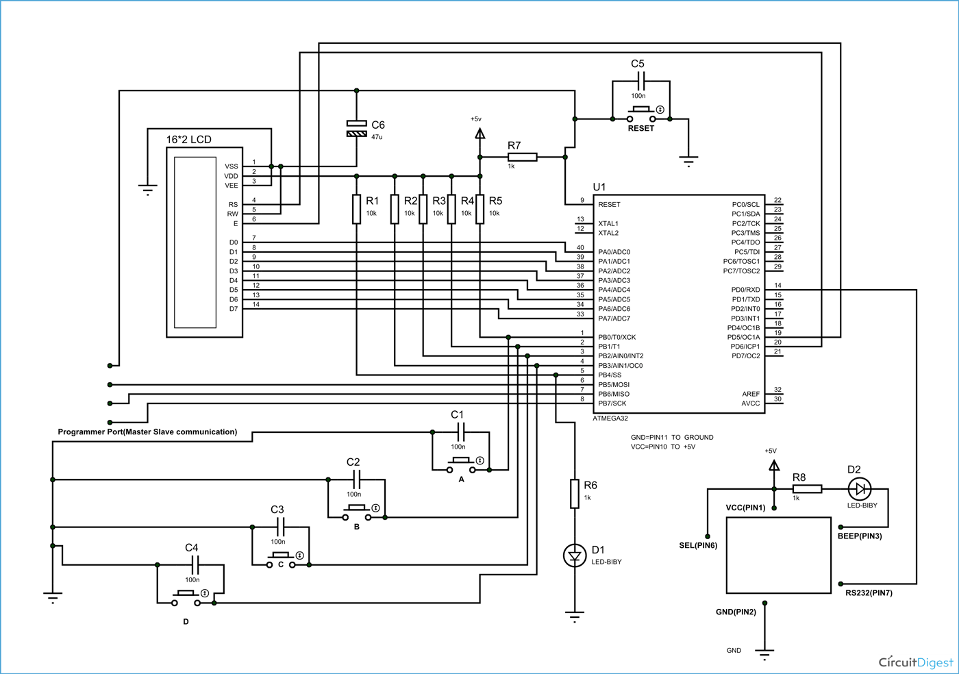
In the toll plaza circuit shown above, PORTA of ATMEGA32 is connected to data port of LCD. Here we should remember to disable the JTAG communication in PORTC to ATMEGA by changing the fuse bytes, if we wans to use the PORTC as a normal communication port. In 16×2 LCD, there are 16 pins over all if there is a back light, if there is no back light there will be 14 pins. We can power or leave the back light pins. Now in the 14 pins there are 8 data pins (7-14 or D0-D7), 2 power supply pins (1&2 or VSS & VDD or gnd & +5v), 3rd pin for contrast control (VEE-controls how thick the characters should be shown), 3 control pins (RS & RW & E).
In the circuit, you can observe that I have only took two control pins. This gives the flexibility of better understanding. The contrast bit and READ/WRITE are not often used so they can be shorted to ground. This puts LCD in highest contrast and read mode. We just need to control ENABLE and RS pins to send characters and data accordingly.
The connections which are made for LCD, are given below:
PIN1 or VSS to ground
PIN2 or VDD or VCC to +5v power
PIN3 or VEE to ground (gives maximum contrast best for a beginner)
PIN4 or RS (Register Selection) to PD6 of MCU
PIN5 or RW (Read/Write) to ground (puts LCD in read mode eases the communication for user)
PIN6 or E (Enable) to PD5 of Microcontroller
PIN7 or D0 to PA0
PIN8 or D1 to PA1
PIN9 or D2 to PA2
PIN10 or D3 to PA3
PIN11 or D4 to PA4
PIN12 or D5 to PA5
PIN13 or D6 to PA6
PIN14 or D7 to PA7
In the circuit, you can see we have used 8bit communication (D0-D7). However this is not a compulsory and we can use 4bit communication (D4-D7) but with 4 bit communication program becomes a bit complex, so I preferred 8 bit communication.
So from mere observation of above table we are connecting 10 pins of LCD to controller in which 8 pins are data pins and 2 pins for control.
Before moving ahead, we need to understand about the serial communication. The RFID module here sends data to the controller in serial. It has other mode of communication but for easy communication we are choosing RS232. The RS232 pin of module is connected to RXD pin of ATMEGA.
For more detail: RFID Based Toll Plaza System

