Description
In working w/ 8 or 14 pin avr devices, I would sometimes want to use the RESET pin as io as the io pin count is low. But doing so will disable further programming via SPI. I do not need a full blown HV programmer, just a way to revert these devices to factory default fuse settings so that i can use SPI to flash them again. it is also handy as sometimes by mistake i may burn wrong fuse value and brick my devices.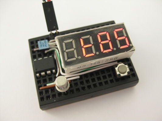
This project is created so that if i could revert the RESET fuse change and flash via SPI again. It employs the high-voltage serial programming (hvsp) available for such devices. Note that this is not to be confused w/ the high-voltage parallel programming used for 20pin+ devices (i.e. tiny2313, mega8, etc).
features
* reads device signature and hi-low fuses for hi-voltage serial programmable attinys
* reset hi-low fuses to factory default on target devices
* layout to drop-on attiny13, attiny25/45/85 8 pin devices targets
* attiny24/44/84 targets needs additional breadboard and jumper wires
* standalone operations, fuses values show on 7 segment display
* cannot reset fuse for attiny2313 and atmega devices as they requires hi-voltage parallel programming
parts list
* attiny2313
* 4×7 segment LED display
* 1k resistor x 2
* 2n2222 NPN transistor or equivalent
* 78L05
* mini breadboard 170 tiepoints
* +12V battery source
project fuse setting
avrdude -c usbtiny -p t2313 -V -U lfuse:w:0xe4:m -U hfuse:w:0xdf:m -U efuse:w:0xff:m
opearation
* place 8 pin target device on breadboard
* for 14 pin targets, jumper wire to breadboard
* apply 12V power
* display shows device name upon identification
* press and release button to cycle display content
* displays device name, fuse hi bits, fuse low bits and fuse extended bits
* long press and release button to reset fuse to factory default
Step 4: Breadboard Layout and Schematic

*Some components shown above are restricted by drawing software (fritzing), see actual photo, the physical layout fits a lot nicer
* The two green pins are to be connected to a 12V power source. I use an A23 12V battery but i can only find a 2xA23 battery holder. You may use whatever is available to you.
* The six red pins are approximate locations for an ISP programmer hookup, you will need to connect the 2nd pin (from left) to pin 1 (RESET, blue wire) of the tiny2313 during programming. In-circuit programming is a hit and miss, as our programming pins are connected to many devices. For the least, you need to remove the led module before attempting to program isp fashion. if fails, you need to remove 2313 and have it programmed off circuit.