Summary of AVR Thermostat
This DIY thermostat uses an ATmega164P microcontroller and a TC1047A temperature sensor to control furnace and AC, featuring a single pushbutton Grayhill rotary encoder for user input and an NJU6355 RTC (with a DS32khz timebase). It is furnace-powered via the C and R wires, stores settings in EEPROM, drives SPST reed relays for outputs, and uses a 16x2 LCD with backlight always on.
Parts used in the Thermostat:
- ATmega164P microcontroller
- TC1047A temperature sensor
- NJU6355 real time clock
- DS32khz timebase
- 16x2 parallel LCD
- Grayhill rotary encoder p/n 62P22-L4 (Digikey GH7295-ND)
- Rectifier diode D2
- Filter capacitor C11
- Voltage regulator U3
- SPST reed relays Hamlin HE321A0400 8006 (RY1, RY2, RY3)
- In-circuit programming connector J1 (optional)
This thermostat is built around an ATMega164 and a TC1047A temperature sensor. It controls your furnace and air conditioner. It is not programmable, although it has a clock and is capable if some additional code were written (any volunteers?). The unique feature is that instead of a bunch of buttons and switches, I used a single pushbutton rotary encoder, for a very simple user interface.
The ATmega164P has plenty of I/O and memory. The LCD is the usual 16×2 parallel I/O. The TC1047A temperature sensor is easy to program to, if you don’t mind its tiny size. The real time clock is a NJU6355. Note the use of a DS32khz instead of the usual 32 kHz crystal; I was fed up with RTCs running a bit fast or slow, and I wanted to try this as a possible solution.* Finally there’s the rotary encoder; I used a Grayhill Inc p/n 62P22-L4. The Digikey part number is GH7295-ND, and the price was C$4.69. (More information on this part can be found on my rotary encoder page.) The encoder outputs a 2 bit code which allows you to tell if it is being turned clockwise or counter-clockwise. In addition it has a pushbutton built in to the shaft. 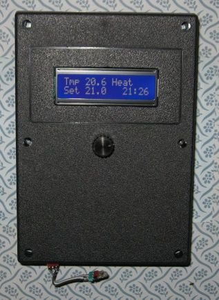
The most interesting part of this project is the use of the rotary encoder. In run mode, turning the knob raises or lowers the temperature setting. Press the button and you enter the customization menu. The first menu lets you select heat, cool, or off. The next menu lets you turn the fan on or off. After a few more menus you can set the clock if you like, then the unit returns to the run mode again.
The nice thing about this thermostat is that it is powered by the furnace. There are no batteries to replace. The last set temperature is remembered in EEPROM so it always returns to the correct state after a power off. What I really like is keeping the LCD backlight on all the time, since there is no need to conserve power.
To make this possible you need access to the “C” wire in the furnace, which is not normally run to the thermostat. My thermostat had “RH” and “RC” wires which were both connected to the “R” terminal in the furnace. All I had to do was move one wire to the “C” terminal (the unused one!).
You may find the terminology of the thermostat/furnace connections confusing, I certainly did. I am not in the heating/AC business so my knowledge is based on study of the furnace schematic and my own speculation. The furnace contains a 24V transformer which powers the control system. One lead of the 24V secondary is common/ground and called “C”. The hot side of the transformer secondary is called “R”. “R” is delivered to the thermostat which contains one to three switches to activate the functions of the furnace and A/C. Each switch requires one wire back to the furnace controller. The one switch all thermostats have is heat, which is returned to the “W” terminal in the furnace. If you have A/C, the cool switch returns to the “Y” terminal. Finally if you have a Fan On switch, it is returned to the “G” terminal.
There may be other kinds of furnace control systems in use. Please make sure your furnace corresponds to my description before you try it. You could damage your furnace controller. I cannot be responsible.
In order to get power from the furnace I accessed the 24 VAC across the “C” and “R” terminals, rectified by D2, filtered by C11 and regulated by U3**. My switches are relays, RY1 RY2 and RY3. I happened to have a few SPST reed relays that operate at 5V and 10 mA, so they can be driven direcly from the AVR I/O port. These relays are labelled “Hamlin HE321A0400 8006”. I rescued them from an old PCB many years ago. (The Fan On relay has been energized in my project for years now and still works!)
J1 (in-circuit programming connector) was used during development but you can leave it out if you like.
Thanks to Peter Fleury for the AVR LCD routines.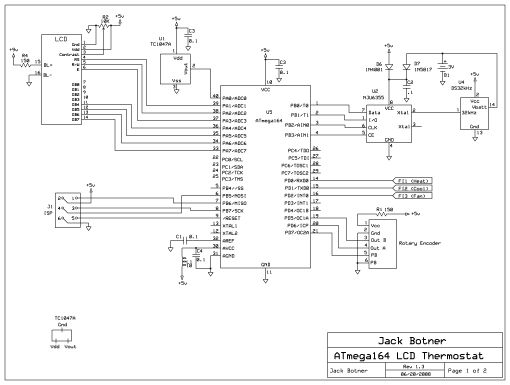
For more detail: AVR Thermostat
- What microcontroller is used in the project?
The ATmega164P microcontroller is used. - What temperature sensor does the thermostat use?
The thermostat uses a TC1047A temperature sensor. - How is the user interface implemented?
A single pushbutton Grayhill rotary encoder (p/n 62P22-L4) provides the user interface. - Does the thermostat require batteries?
No, it is powered by the furnace via the C and R wires so no batteries are required. - How are furnace and A/C controlled?
Functions are switched using relays (RY1, RY2, RY3), which are SPST reed relays driven from AVR I/O. - Is the thermostat programmable?
It is not currently programmable, though it has a clock and could be made programmable with additional code. - How does the clock maintain accuracy?
The design uses an NJU6355 RTC paired with a DS32khz timebase instead of a 32 kHz crystal to improve accuracy. - How are settings retained after power loss?
The last set temperature is stored in EEPROM so it returns to the correct state after power off. - What components provide power regulation from the furnace?
AC from R and C is rectified by D2, filtered by C11, and regulated by U3 to power the unit. - Is an in-circuit programming connector required?
J1 was used during development but can be omitted in the final build.