Introduction
This project implements a 2D matrix of bidirectional LEDs to simulate how fireflies in a population synchronize their flashing.

Fireflies are an extraordinary species of bioluminescent animals which are able to synchronize the timing of their light emission within a flashing population. In places such as Thailand and Malaysia, during night at the right time of the year, one may be able to witness a hilltop or tree lit with thousands of tiny yellow lights flashing in nearly perfect synchrony. These lights emanate from the lanterns of thousands of individual fireflies constantly evaluating their immediate surroundings and adjusting the frequency and phase of their own flashing. (Further biological information can be found Here ) This phenomenon is fascinating because the network of fireflies synchronizes without direction from a central and/or leading individual. For all intensive purposes, these fireflies exhibit spontaneous synchronization over large networks and without directive forces. The exact mechanism for how fireflies synchronize their flashing is unknown, but there is significant interest in mimicking this synchronization using computer programming. An important application for this type of synchronization is in wireless ad hoc networks, in which the network is made up of a large, dynamic collection of individual nodes which must efficiently coordinate with one another to meet individual needs. Therefore, modeling ad hoc networks after biological systems may potentially be more efficient that current networking schemes allow. The goal of our final project was to build a LED-based device running on a microcontroller chip to mimic how fireflies might theoretically synchronize their flashing in nature. The device serves as a future model on how to implement a physical form of networking using a microcontroller chip.
To implement these goals, we created a 2D matrix of 8 fireflies. Each firefly is represented by a node in the 2D grid, and a connection between any 2 nodes is represented by a pair of 2 LEDS: an emmiter LED and a sensor LED. The fireflies are able to concurrently communicate and sense the signals emanating from surrounding fireflies using a form of one-directional LED communication. Each firefly is equipped with a fixed number of emitter LEDs and a fixed number of sensor LEDS, depending on the position of the LED within the matrix. For simplicity, we assumed that the fireflies positioned were fixed in time, i.e. they were not able to travel. The firefly flashes using one set of LEDS, the emitter LEDs; the firefly senses the surrounding fireflies flash using another set of LEDs, the sensor LEDs. To accurately mimic the way fireflies in nature sense neighboring signals, we decided that the emitter LEDs must be electrically isolated from the sensor LEDS, i.e., communication from one firefly to another is done through optical signaling. Each firefly is equipped with an individual (i.e. independent) brain in the microcontroller code that processes the signals that it has sensed and tries to synchronize its own flashing with these surrounding fireflies. Like in any real world situation, each firefly flashes with a random frequency and phases and it adjusts these flashing parameters to conform to the overall flashing of the localized population.
High Level Design
Our project idea came from Professor Steve Strogatz’s work in Cornell University’s TAM department, a leading professor on dynamic, nonlinear systems. He wrote a paper mathematically modeling firefly synchronization (Duncan J. Watts, Steven H. Strogatz (June 1998). “Collective dynamics of ‘small-world’ networks“. Nature 393: 440-442.). After careful consideration of our hardware constraints, we decided to implement a much simpler synchronization scheme in our system. Our goal was to minimize the complexity of the computations in order to maximize the efficiency of the microcontroller program and the time of convergence (the time it takes the system to synchronize the flashes from all of its entities). Therefore, the two goals of the high level design were as follows: 1) The algorithm for synchronization ultimately had to converge. 2) The computations contained within this algorithm must not significantly slow down the processing speed of the program. To satisfy these 2 goals, we decided to simply average the frequencies of nearby fireflies for each individual firefly, and set the new frequency of flashing for each individual firefly to this average value. This simply algorithm is iterated until convergence of flashing is noted. It is also important to note that the convergence of the system is ideal when the number of random, independent entities is very large. However, we could only construct a relatively small matrix of LEDs because of power limitations coming from the development board used to support the microcontroller chip. Additionally, we were limited to a small number of fireflies because of the limited number of i/o pins on the development board. Ultimately, we decided to have a much smaller array (3×3) than the large (not infinite) number that Strogatz assumed in his paper.
Unfortunately, this synchronization scheme did not work successfully because of 2 reasons: First, we had to implement edge effects in the array. These undesirable effects resulted from the fireflies that had exactly three neighbors, an odd number. Each of these fireflies received 3 optical signals, added them together, and then added one more of the neighboring signals (repetition) so that the average could be calculated by taking this new sum and simply shifting right by 2 bits. We did not want to do any direct multiplication or division in the code since the computation time would increase greatly and slow down the code. A larger array of LEDs is better, because the edge effects will have a small (degrading) contribution to the overall system. However, even if we had used a much larger LED array, then this scheme of the averaging neighboring signals would only partially work, as will soon be discussed.
The second reason for non synchronization is that the method of averaging that we used to calculate the next state of the system created a nonlinear system. As we learned in ECE 320 and TAM 578, nonlinear systems are very difficult to solve. The most convenient method of solving nonlinear systems is to plot a x vs. x΄ graph, look for basins of attraction and then determine initial conditions for the system that will ultimately converge the system into one of the possible basins of attraction. Therefore, our system of 8-fireflies will not be able to completely synchronize because we essentially built a nonlinear system by using difference equations to compute the next iterative state of our system. However, there are ways to force this nonlinear behavior into a linear behavior to make the system converge, and one of the most convenient ways is to use a very small system containing only 2 or 3 fireflies.
For a very large number of nodes (fireflies), our system theoretically has 2 steady states: One state is where all of the LEDs are made to flash at the same frequency and phase, and the system always stays in this state. The other steady state is where alternatively placed fireflies flashing out of phase with the rest of the fireflies. For example, even number labeled fireflies would be made to flash exactly out of the phase with odd number labeled fireflies. If this device is working properly, then the even and odd fireflies will keep swapping their phases with one another. These particular steady states have certain implications for our device: First, there are only 2 basins of attraction for this system and these can be used as a proof of concept that can easily be implemented on our device. Second, neither of the steady states will result in the synchronized flashes.
Initially, the goal of this project was to simply mimic how fireflies flash in nature, but we have now developed our project into a physical investigation of how a nonlinear systems changes in response to an increasing number of nodes (in our case, fireflies).
Program/Hardware Design:
Hardware
The Atmel AT90 Mega-32 MCU chip, an 8-bit microcontroller with programmable in-flash memory, was supported by a STK500 AVR Flash MCU evaluation board. This board is essentially a development board complete with pushbuttons, LEDs, 4 ports, serial connections (programming and application), and a 16 MHz crystal. PORT A was connected to the emitter LEDs. PORTB, PORTC and PORTD were connected to the sensors LEDs via the 2X non-inverting operational amplifier and the Schmidt Trigger.
The schematic directly below (Figure 5) shows the hardware needed to generate the flashing by connecting the emitter LEDs to the MCU and ground.
The right hand side of Figure 5 shows the emitter LED of each firefly. The LED is tied directly to the output pins of the MCU, which are square-wave signals in our program. Connecting the emitter LEDs for the center firefly proved to be a little difficult, because for this LED a total of 4 emitter LEDs had to be connected to one i/o pin. The LEDs were connected in parallel; connecting the LEDs in series would only be able to successfully power 3 of the 4 LEDs connect 3 because they require at least 1.7V to turn on and 5V power supply can only accommodate three 1.7V drops in the voltage. In parallel, the LEDs are current-limited but this scheme allows for the 4 LEDs to be connected to one output i/o pin. No resistors were used because we wanted the emitter LEDs as bright as possible to be able to communicate with sensor LEDs. The current and voltage under this scheme agreed with values provided with the LED spec sheet, and they worked well as a result.
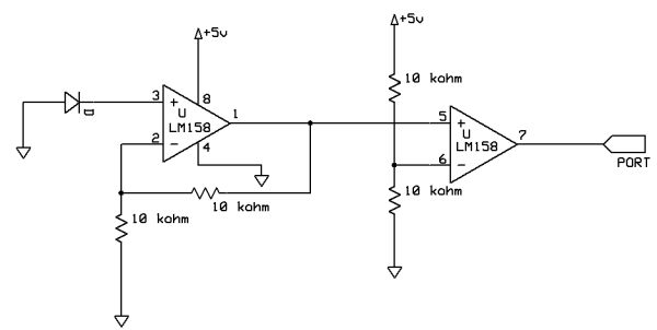
The schematic directly below (Figure 6) shows the hardware needed to receive the signal from the sensor LEDs and digitize it so that the MCU will be able to recognize it as valid logic values.
This circuit consists of a 2X non-inverting operation amplifier (simple negative-feedback with R1 and R2 at the same resistance) and a Schmidt Trigger circuit. Both the negative-feedback operational amplifier and the Schmidt Trigger were constructed from LM358 IC chips, which are not rail-to-rail operational amplifiers. The first stage of our hardware was a 2X non-inverting amplifier. The output of the sensor LED is feed into the positive input of the LM358 op amp connected in a negative feedback loop. The gain of a simple negative-feedback op amp circuit is calculated below:
Vout = Vin * ( 1 + R2/R1)
Gain = Vout / Vin = (1 + R2/R1)
Since R1 = R2, Gain = 2.
10 kΩ PACKAGED resistors with 1% accuracy were used for R1 and R2. We needed to amplify the signal coming out of the sensor LED, because LEDs can only serve as weak photodiodes. The signal emanating from the sensor LED had an amplitude of roughly 1.2V, and therefore, the output of the op amp was approximately at 2.5V. The signal then passes from the op amp to the Schmidt Trigger, where it can be converted to a digital signal for input into the MCU. Therefore, the Schmidt trigger acts as an A/D converter. We had it set to trigger at 2V, knowing that an ideal high signal coming into the trigger will be greater than 2V. Since the Schmidt trigger is not constructed from a rail-to-tail op amp, the output of the trigger had a true high logic signal but an ambiguous low logic signal. The code was not able to recognize the following statement: arg1 == 0. According to Horowitz and Hill in The Art of Electronics the LM358 uses a PNP follower to ground which can only pull down to within a diode drop of ground (229). Therefore, it makes sense that the lowest voltage we could output from the trigger was 0.7V. Therefore, a comparison with 1 is done by either writing arg1 == 1 or arg 1 =~ 1. The end of the two stages produces a reasonable digital signal, with a small but manageable amount of superimposed noise.
Our LED communication was based mainly on proximity. It worked well when the two LEDs were in the same plane and directly facing each other, as can be seen in Figures 2, 3, and 4. If the LEDs were not in the same plane but were instead at an angle, the signal would drop off exponentially until there was essentially no signal at an angle above 10 degrees separation. By trial and error, we were able to determine that the red and clear LEDs worked equally well as emitters compared to the yellow and green ones. The red LEDs worked better as receivers. This might be due to the fact that the red epoxy could amplify the red signal more than the other light sources. Therefore, we tested the one-directional LED communication with a clear LED serving as the emitter and a red LED serving as the sensor. The signal received by the sensor LED was fairly clean (minimal noise) and therefore neither analog nor digital filtering was included.
We ran into several problems when we tried to duplicate the circuit. From Lab 1, we knew that the STK500 could only handle 10 LEDs lit off of it. However, we attached 20 LEDs to the development board in this project. The LEDs would flash 2 to 3 times before the MCU chip was completely turned off (automatic chip safety routine kicked in when we tried to draw too much power to the LEDs). It took us a while to realize that the STK500 couldnt provide enough power, because we initially suspected that our device has a short somewhere in the wiring. Once we realized it was a case of insufficient power, we connected an additional 5 V power supply the STK500 to power up all of the LEDs. The Proto-board PB-503 served easily as the 5 V power supply. We connected the ground pin to the ground on the proto-board and the Vcc to the 5V power supply on the proto-board. Once the power issue was solved, the circuits were all soldered onto PCB boards and stacked them into a cube to minimize the dimensions of the device.
Software
Our software design was based on the scheme outlined in the high level design, in which we used an averaging algorithm to try to synchronize the flashing. Our main concern with the code was trying to minimize the number of variables and/or length of the code that we used and to try and keep our computation as simple as possible. To keep the computation simple, we only divided by 2 and 4 so that shift right commands would always be applicable to the computation.
The flashing of each LED was done using a counter and if statements. During the first part of the count the LED would be assigned high and during the latter part of the count it would be off. This count is the same for each LED; each LED is on for 5 counts and off for 5. It then resets itself. The rate at which the count is done is what changes for each of the LEDs. This is set randomly in the initialize function. This flash continues throughout the calculations and only gets reset when the calculations are done to restart the phase.
This section aims to do the following: explain the reasoning behind the design of the state machine and tasks that comprise our overall program. This will be done by outlining the function of each state/task and how it contributes to the overall program. (The sections following this one will cover the debugging and testing of the code.)
C Libraries:
The following libraries were included: Mega32.h, stdio.h, stdlib.h, and string.h.
Interrupt Function:
Only one hardware interrupt were used in this program: The Timer 0 Compare Match interrupt was used to decrement the counters used as counters to get the emitter LEDs to flash at their appropriate frequencies. It is also used to increment countdelay variables used to time the period of the neighboring LEDs.
Main Function:
The main function first calls the initialize function. It first calls the 8 emitter LED functions ledflash#() from the timer set by the Timer0 compare match ISR. Then it calls the 8 sensor LED functions updatfreq#(). The syncflash function is called when the condition that all the fireflies (blocks) have figured out all the frequencies of their neighbors flashing.
Initialize Function:
Called from the main function, the initialize function does the following commands:
First, the data flow was set such that PORT A is an output (to get the emitter LEDs to flash). PORT B, PORTC and PORTD are inputs (to get the signal from the sensor LEDs and send it to the MCU for analysis), and PORT D is an output (for the ADC output). The Timer 0 Compare Match ISR is set to occur every 1 ms by setting the compare register to 249 and the prescalar to 64 and turning on the clear-on-match option. The LEDs are initialized off. Default states for switch statements, timers, flags and global variables are set to initial values. The timers for the ledflash#() functions are set to random integers by calling the rand() macro. This was done to generate 8 different frequencies for the 8 different blocks of emitter LEDs. Last, global interrupts are enabled using the assembly language command sei.
The Ledflash# Function:
The 8 Ledflash# functions are called directly from the Main function via the Timer0 compare match interrupt. Its timer is reset at the beginning of the code. Then the LED is turned on for first 5 counts (5 * 1 ms * the random period of flashing), and LED is turned off for the rest of the random period.
Updatefreq#and SyncFlash Functions:
The 8 Updatefreq# functions are called directly from the Main function via the Timer0 compare match interrupt. Its timer is reset at the beginning of the code. The function is comprised of a switch statement for each neighbor LED, and the switch statement was written to evaluate the period at which the neighbor LED flashes. Once all the neighbors have been evaluated exactly once, them the periods of the neighboring flashes are averaged, and a buffer variable timebuff# will be set to this average value. Once all the fireflies have successfully evaluated their neighbors, then the syncflash function will be called to simultaneously update the periods of the flashing emitting LEDs. Notice that the emitter LEDs are updated simultaneously; this is done to set all the phases to zero, and therefore, the phases of the flashing will not have to be tediously computed by the microcontroller.
Debugging the Hardware and Code:
We looked at ordering multiplexers to connect the 24 sensors LEDs to the 8 A/D converters provided on the Mega32 chip. However, we decided to build 20 analog 1-bit A/D converters out of Schmidt Triggers, which were made out of LM358s available in lab. This allowed us to run 20 analog-to-digital conversions simultaneously, while the ADC on the Mega32 would only have allowed us to collect 8 bits at one time. We built and tested the sensor hardware circuits first on a protoboard and then soldered them to PCBs. The other significantly difficulty with the code was determining how to write code for our non-ideal signals, where the analog low wasnt equivalent to a logic zero (+ 0.7V). The LM358 op amps were not rail-to-rail, and this affected the output of our ADC, because the low signal was at 0.7 V. We circumvented this problem by writing all the logical comparisons with reference to 1s and not 0s.
 fly,
fly,
We first tested the software for a small array shown in Figure 4, a 3-insect array. We started with a small array of fireflies to if the code could converge for small system of fireflies (nodes), and then we increased the number of fireflies to 4, and then to 8. Our first hurdle writing the code dealt with getting the emitter LEDs top flash randomly. It was relatively easy to make the emitter LEDs flash with different frequencies, and this is what we ended up implementing for the final project. However, getting random phases proved to be much more difficult. We were able to implement delay_us() macros to get the phase delays, but we were unable to vary the order in which the LEDs would flash. But for all intensive purposes in this project, using solely random periods creates a sufficiently random initial state for the system.
Parts List:
| Part | Qty | Price | Total Cost |
| PCB Board | 4 | $2.50 | �$�� 10.00 |
| STK500 | 1 | $15.00 | �$�� 15.00 |
| LED | 40 | $0.50 | �$�� 20.00 |
| LM358 | 20 | $0.12 | �$��� 2.40 |
| TOTAL | �$�� 47.40 |
For more detail: Firefly synchronization Using Atmega32