Introduction
A perfect tool for high school students that will pursue a career in engineering, the graphing and statistics calculator combines the functionality of a scientific calculator with graphing capabilities as well as being able to compute simple statistics.
The purpose of this calculator is to compete in the graphing calculator market with the common Texas Instrument standard, specifically the TI-83 and TI-89. Our calculator is more simplistic and has no outer case due to the limited budget provided. Comparatively, the finished product is budgeted at a price (~$50) that is competitive with other graphing calculators on the market today. Lastly, the implementation of a PS/2 keyboard allows the user to have more ease in typing rather than having to use the “alpha” key to write text.
Higher Level Design
The concept for this project came as a result of determining what was realistic within the limitations of our budget. Our main concern was building something that was not a hit or miss, meaning that the final product did not have to be fully complete to be presented. The calculator was perfect for this because we could implement the software in an incremental fashion with three major parts.
Prior to dealing with the software, it was essential to have the hardware functioning first. We decided to use a Nokia LCD knockoff as the display because it was recommended by Professor Land through a link on the class website. The LCD had many distinct advantages: it was moderately priced at $20, it supported color which allowed us to distinguish separate equations, and there was sample Mega32 code written by other people that could be used rather than having to write from scratch. After getting it soldered and operational, we were able to focus on putting together the calculator itself.
The first major part of this project was coding for the PS/2 keyboard. After researching with Google, a table of scan codes and a pin-out diagram were found. The output was relatively simple to verify because the bits were checked using an oscilloscope against the scan code table. Though it was a crude process, it proved to be effective in verifying its functionality.
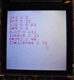
The second integral portion involves building the scientific calculator, which includes basic math such as addition, subtraction, multiplication, and division. A crucial consideration had to be taken here because of the order of operations, which required special attention to ensure that the equation string received from the keyboard to be evaluated is computed properly. The functions written here (doMath and doCalculation) were also used to calculate points to be plotted on the graphing side.
The last important piece of software was the graphing calculator. It allows the user to input equations with a range for xmin, xmax, ymin, and ymax. However, due to the complicated LCD scheme explained later, the features of zoom and scaling were not able to be implemented. The statistics portion was also written to add unique features to the product.
In terms of hardware to software tradeoffs, the most challenging aspect was the LCDs interaction with the hardware. There were definite temptation to push the LCD to refresh at a faster pace; however, it had limitations with fading effects. The display could also support more colors than we had utilized, but it was not worth the overall tradeoff in terms of speed. In the scope of the project, no standards were followed other than the ANSI C because we coded in the C language. Regarding patents, trademarks, and copyrights, there was no violation because all the code was either written by us or protected under the GNU General Public License.
Hardware Design
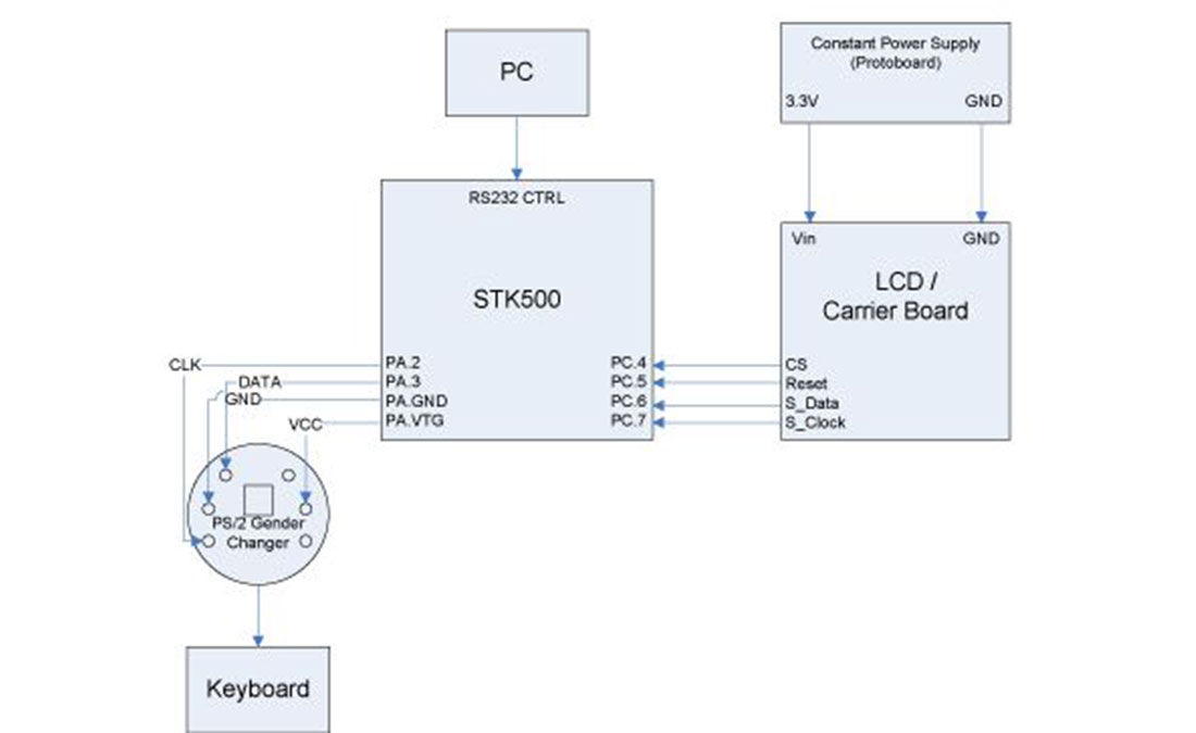
The main pieces of hardware involved in our calculator are an LCD display for showing the user inputs and graphing the output, a keyboard of dynamic entry (text, numbers, and math symbols), and the STK-500 for the Mega32 microcontroller. The LCD was an LCD ordered off Sparkfun.com. The keyboard was a standard PS/2 keyboard. When testing, we used both Dell and IBM keyboards, but since both followed the more common industry standard of scan code set 2, there was never any problem using the keyboards. The STK-500 was the standard classroom board that we have been using all semester. Even though we did not use most of the functions on the STK-500, we opted not to use our own printed circuit board because it was extremely convenient to have some of the indicators on the board for development.
The LCD screen was the same model used by another project group this year and bought from SparkFun for $20. In addition, we ordered two other parts: a connector piece for the LCD and a carrier board. The connector piece was $1 and allowed the LCD to be soldered to other components. The carrier board was $15 and served the same function as the connector piece, but all the ports were already pre-printed. At first, we were afraid that the LCD was very delicate and we handled it very carefully when putting it into the carrier board. There was no distinct “snap” as the LCD fit into the carrier board. Rather, we felt a “crunching” sensation as the pieces interlocked. We became worried that LCD connectors were broken, but upon prying the piece away from the carrier board, we found everything was intact and proceeded with the project. The next step was to try and load up the Mega32 driver code for the LCD. We realized early on that there was timing issues with the refresh rate because of the difference between the clock speeds of what the driver was written in (4MHz) and what our Mega32 ran at (16MHz). Initially, we attempted to compensate for this problem by quadrupling all the delays in the driver, but that did not seem to help and the default display did not appear. To solve the issue, the Epson command set and color set were added to fix the issue.
The keyboard presented a bigger challenge then we would have expected. By doing a little research, we knew how the PS/2 keyboard worked. With 6 output pins in the device, only four of them were used: Vcc, ground, clock, and data. The PS/2 keyboard works by supplying power and ground to the keyboard (the recommended values are 5V at 300mA, but we supplied 7.5V at approximately 500mA). Once a key is pressed, the keyboard generates is own clock signal and a data signal that it passes through the respective lines. In order to decode which key was pressed, the host must read the data line on the falling edge of the clock. In all, 11 bits of data are collected per key stroke. The scan code syntax is 1 start bit, 8 data bits, 1 parity bit, and 1 stop bit. The 8 data bits are passed in with least significant bit first, which means essentially that the scan code is “backwards” from what a normal human was expect. In addition, both lines float high when idle (so the start bit is always logic 0 to signal the start of a data stream). The keyboard clock is not an accurate crystal. The published data shows that a keyboard clock cycles approximately 10-16 KHz. This translates to roughly 60-100us periods or an average of 80us. If a key stroke is pressed from for a designated amount of time, the key starts to send repeat patterns to the host (so the key will start to replicated very quickly to the host machine). If the key is released, the keyboard sends a known “break” command to the host (0xF0) followed by the key that was just released. This creates at least 22 bits for the ending sequence of the keyboard. Because we are using our keyboard in a very limited function (all 26 alphabetical keys, both the top-row and keypad numbers, and miscellaneous buttons such as enter, asterisk, divide, period, etc.) we did not deal with any of the “strange” scan code keys (such as break/pause, which has a 64-bit scan code). In addition, we were not too concerned with the fidelity of the scan codes, so we do not worry about the start, parity, and stop bits. Also, since the user should not be pressing more than one button down at a time, we also ignored the break code and its corresponding bits at the end. This essentially leaves us with 8 bits of real data, of which our only task is to flip the bits (to put MSB on the left end of the array and LSB on the right end) and then compared to an array look-up table. The keyboard input was read using a 10us interrupt on the Mega32. The interrupt would poll the keyboard input line (A2 for clock, A3 for data) to check and see if the clock line was low. If the clock line was low, then it would accept the data value on the data line into an array. We polled the line every 10us to over-sample the keyboard on purpose. Because of the variability in the keyboard clock, we would not count on an 80us interrupt to achieve enough accuracy. Because the PS/2 keyboard is a male connector, we used a female-to-female PS/2 gender changer adaptor that changed the PS/2 keyboard connector into a female connector; the adaptor allowed us to easily connect wires to the PS/2 keyboard and to integrate with the STK-500 board.
The STK-500 board has a number of built-in handy devices that our calculator ended up not using. One extremely useful component was the LED array, which we used to detect which state our software state machine was in, in addition to debugging initializing problems. The STK-500 also had an interface with the computer (Hypertrm) via an RS-232 cable. We also used Hypertrm extensively in our initial development, but in the final product, we opted to move everything onto the LCD display to decrease on the number of peripherals and dependencies that the graphing calculator would have. Lastly, another convenience that the STK-500 afforded us was readily available “ports” that we could plug our external devices such as the LCD and keyboard into. Aside from that, the decision not to use a smaller Mega32-only board was that the difference in price ($2 net change) was not a suitable tradeoff. Otherwise, the only real component we used on the STK-500 board was the Mega32 chip.
Parts List:
| Part | Cost |
| Standard PS/2 Keyboard | Free |
| PS/2 Gender Changer | Free |
| Color LCD 128×128 Nokia Knock-off | $19.95 |
| LCD Carrier Board | $14.95 |
| STK-500 (with Mega32) | $15 |
| Power supply (3V) | $5 |
| Total | $54.90 |
For more detail: Graphing calculator Using Atmel Mega32